
CW Practice oscillator

The proposed circuit employs the NE555 timer in an astable configuration to generate a square wave output, which can be used to produce Morse code signals. In this setup, the timer continuously switches between its high and low states, creating a tone that can be modulated to represent Morse code. The frequency of oscillation, which dictates the speed of the Morse code output, is influenced by the resistors R1 and R2, as well as the capacitor C1.
The relationship governing the frequency (f) of the output waveform can be expressed by the formula:
f = 1.44 / ((R1 + 2 * R2) * C1)
Where:
- R1 is the resistance connected from the discharge pin to VCC,
- R2 is the resistance connected from the discharge pin to the threshold pin, and
- C1 is the timing capacitor connected to the threshold pin and ground.
Adjusting R1, R2, or C1 will allow users to modify the frequency of the output signal, thereby enabling the generation of different Morse code speeds.
The circuit requires a 9V PP3 battery for power, which is connected to the VCC pin of the NE555 timer. The output pin of the NE555 timer can be connected to a speaker or a piezo buzzer to produce audible tones. Additionally, a simple switch can be included to enable or disable the output signal, allowing for convenient operation during practice sessions.
Overall, this circuit serves as an effective tool for amateur radio enthusiasts to practice and improve their Morse code skills, providing a hands-on approach to learning and enhancing communication abilities in the amateur radio community.A circuit diagram that can be used for the generation of CW Morse code is shown here. This circuit can be very useful those who would like practice Ham Radio. The circuit is nothing but an astable multivibrator based on NE 555. The frequency of oscillations of the circuit depends on the components R1, R2 & C1. The circuit can be powered from a 9V PP3 b attery. 🔗 External reference
Related Circuits
In the Hartley circuit, the amplified energy from the plate circuit is fed back to the grid circuit through fluctuating magnetic fields. Both circuits utilize magnetic feedback. The Hartley circuit employs a single coil, with part of it situated...
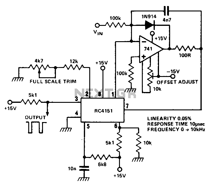
The RC 4151 precision voltage-to-frequency converter generates a pulse train output that is linearly proportional to the input voltage. The RC 4151 is a highly accurate voltage-to-frequency converter designed for applications requiring precise frequency output based on varying voltage levels....
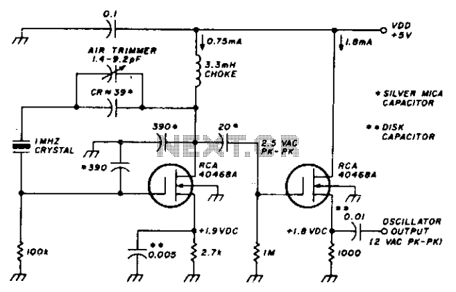
This stable oscillator circuit exhibits less than a 1 Hz frequency change over a VDD range of 3 to 9 volts. Stability is attributed to the use of MOSFET devices and stable capacitors. The described oscillator circuit is designed to...
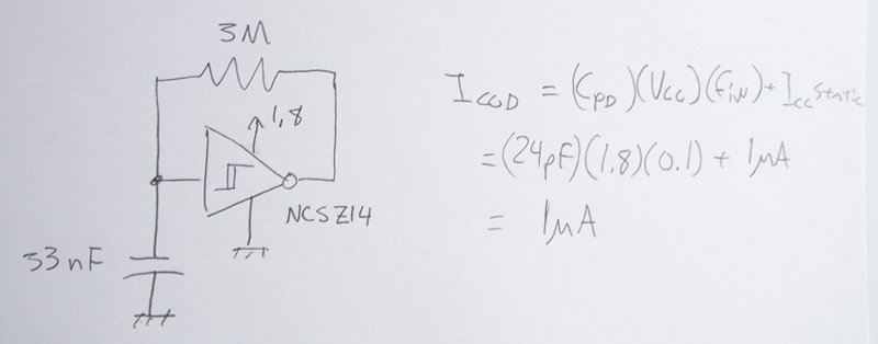
The power supply varies, and the circuit must operate at under 10 µA of current (excluding the capacitor charging). It triggers a Silicon Controlled Rectifier (SCR) every 10 to 30 seconds as long as the power supply is above...
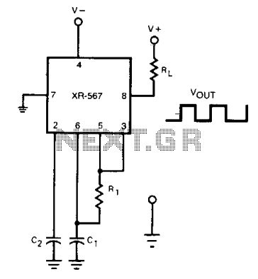
The frequency of the current-controlled oscillator can be doubled by feeding a portion of the square-wave output from pin 5 back to the input at pin 3. This configuration allows the quadrature detector to operate as a frequency doubler,...
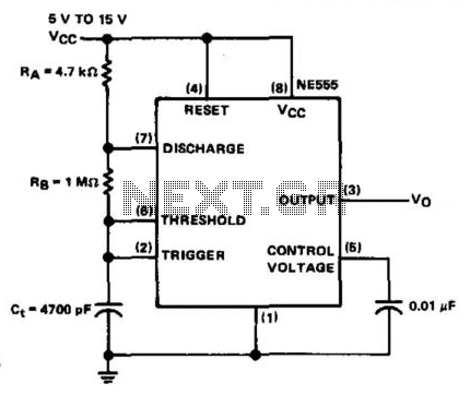
The NE555 timer is configured in astable mode and utilizes three timing components (RA, RB, and Ct). A 0.01 µF bypass capacitor is connected to pin 5 to enhance noise immunity. The operational limitations of the astable mode are...