
LM1875 IC For 20Watt Audio Amplifier Circuit

The 20-Watt audio amplifier circuit utilizing the LM1875 IC is a robust solution for automotive sound systems. The LM1875 is a high-performance audio power amplifier capable of delivering up to 20 Watts of output power with low distortion and high efficiency.
The circuit typically includes a power supply section that provides the necessary voltage and current for the LM1875. A common configuration employs a dual power supply, offering ±16V to ±20V, ensuring optimal performance.
Input signals are received through a coupling capacitor, which blocks any DC components while allowing the AC audio signal to pass through to the amplifier. The gain of the amplifier can be set using external resistors, allowing for customization based on specific application needs.
The output stage of the LM1875 connects to a load, such as a speaker, typically rated at 4 to 8 ohms. To protect the circuit from potential damage due to overcurrent or overheating, a heat sink is often mounted on the LM1875, facilitating heat dissipation during operation.
Additional components may include feedback resistors to stabilize the gain and capacitors for filtering and bypassing noise, ensuring high-quality audio output. The circuit can be integrated into a car's audio system, providing enhanced sound reproduction for an improved listening experience.
Overall, this audio amplifier circuit is a practical choice for automotive applications, delivering reliable performance with a straightforward design.The following circuit shows a 20Watt Audio Amplifier Circuit Diagram Based On The LM1875 IC. Features: applied in a car, 20Watt audio amplifier, 4 .. 🔗 External reference
Related Circuits
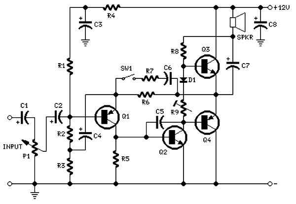
The circuit is intentionally designed using older type transistors to achieve harmonic distortion and to mitigate the challenges of sourcing high-quality components. The amplifiers can be easily powered by a plug-in wall transformer rated at 12V. When SW1 is...
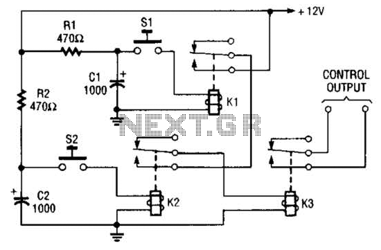
Due to the limited hold-on time of the delay circuits R1/C1 and R2/C2, both switches S1 and S2 must be activated simultaneously to energize the load. The circuit in question involves a delay mechanism governed by the time constants associated...
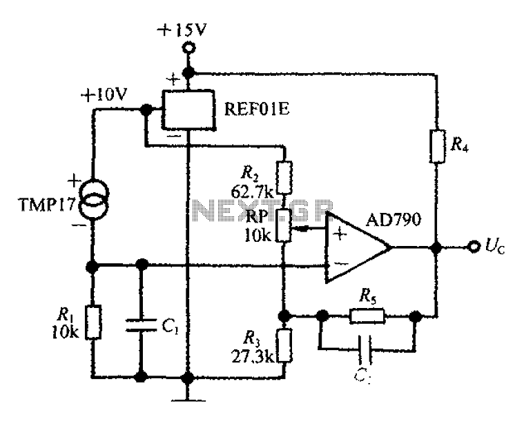
An adjustable thermostat controller circuit is widely used in everyday applications, such as for maintaining a constant temperature in soldering irons. The circuit utilizes the TMP17 sensor along with the REF01E voltage reference to ensure a stable 10V supply...
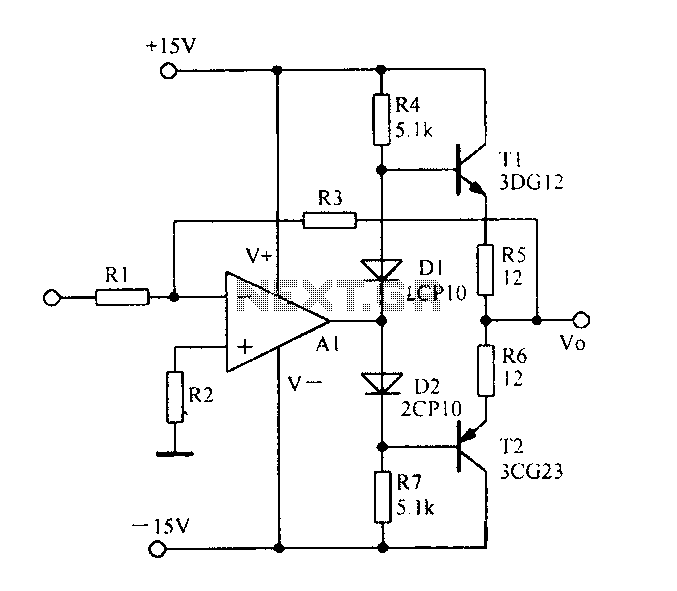
Current spreading bipolar output when the circuit diagram is as follows. The circuit described involves a current spreading bipolar output configuration. This type of circuit is typically used in applications requiring efficient current distribution across multiple output paths, often seen...
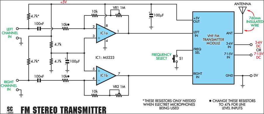
This stereo FM wireless microphone serves as an excellent audio link. Testing revealed a reliable range exceeding 50 meters. It is distinct from previous wireless microphones due to its stereo capability, which delivers unexpectedly high-quality sound. The range was...
It is well known that pests like rats, mice, etc., are repelled by ultrasonic frequency in the range of 30 kHz to 50 kHz. Human beings can't hear these high-frequency sounds. Unfortunately, all pests do not react at the...