
Short Range Personal Radar Circuit

The circuit design integrates several components to achieve the desired functionality. The power supply circuit is crucial for providing a stable voltage to the entire system. The LM7805 voltage regulator is selected for its reliability in converting the 9V battery output to a consistent 5V, which is essential for the microcontroller and other components to operate efficiently. The inclusion of a 1µF capacitor at the output ensures that any voltage fluctuations are smoothed out, thereby enhancing the stability of the power supply.
For programming the PIC microcontroller, the design allows for direct connection to a programming device via two designated pins. The connection to the MCLR*/Vpp pin is vital for resetting and programming the microcontroller, while the rectifier diode serves to protect the circuit from potential back EMF or voltage spikes, ensuring the longevity of the components.
The IR proximity sensor is a key element in this project, providing real-time data about the presence of objects in the vicinity. By utilizing the analog input capabilities of PIN 2 - RA0, the microcontroller can convert the analog voltage signal from the sensor into a digital value using the onboard ADC. This value can then be processed to determine the proximity of objects, enabling the system to respond appropriately.
The LED display serves as a visual output mechanism to convey information based on the proximity sensor's readings. With a total of 40 LEDs, the design employs five 74HCT373 chips to manage the LED control. Each chip can handle 8 LEDs, and the common data bus facilitates communication between the microcontroller and the chips, allowing for synchronized control of the LED outputs. This arrangement not only simplifies the wiring but also enhances the overall efficiency of the design, enabling a clear and effective display of the sensor's data.
Overall, this circuit schematic represents a comprehensive approach to integrating various electronic components to achieve a multi-functional system capable of programming, sensing, and visual output.The schematic for this project is much more complicated than previous projects. There are four main features in our design. (1) We will be able to program the pic on the board we develop. (2) We will be controlling a servo. (3) We will be taking data input from an IR Proximity sensor. (4) We will set 36 LEDs to display proper output to respresent what the IR sensor sees. The power circuit is a 9v Battery hooked up to the LM7805 with a 1uF capacitor hooked to output & ground of the LM7805 to keep a steady 5v DC. The programming circuit is made by hooking up two pins from the PIC to the programmer and allowing the programmer`s pin 1 access to the MCLR*/Vpp-Pin1 on the PIC.
We put a rectifier diode in there for safety as well. The IR Sensor only uses 1 pic from the pic, PIN 2 - RA0. It will use the analog feature of this pin to get an ADC value as the proximity sensor only outputs analog voltages. This value will tell us the if anything is near the sensor in our enviornment. There are 40 LEDs in total. Since each 74HCT373 can control up to 8 leds; 40/8 = 5 we`ll need to use 5 74HCT373`s to be able to control all 40 LEDs.
It is important to notice on the schematic that a common data bus is used between all the 5 chips. 🔗 External reference
Related Circuits
The crystal radio derives its name from the galena crystal (lead sulfide) utilized for rectifying signals. A "cat's whisker" wire contact was adjusted on the crystal's surface until a diode junction was established. The 1N34A germanium diode serves as...
The liquid level controller circuit comprises a power supply circuit and a level detection control circuit, as illustrated in the accompanying chart. The power supply circuit includes a power switch (S1), a power transformer (T), bridge rectifiers (UR1, UR2),...
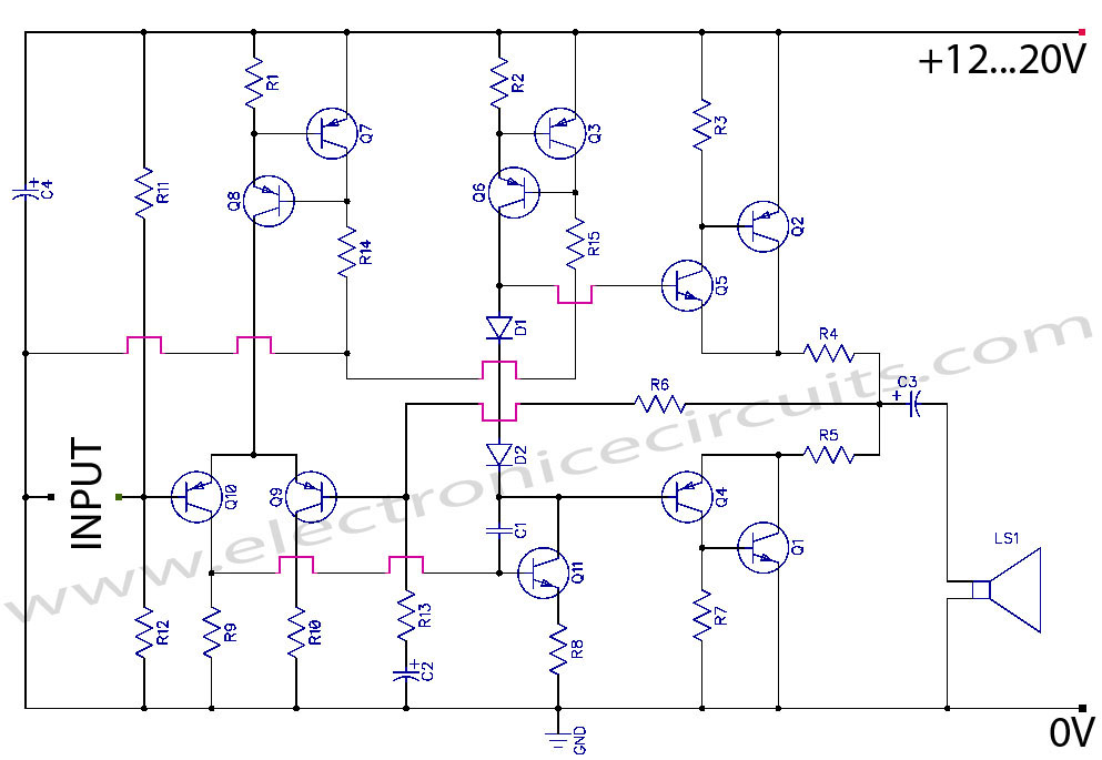
Discrete Class AB Transistor Audio Power Amplifier Circuit Diagram. This is a Class AB transistor power amplifier. It is a simple amplifier to... A Class AB transistor audio power amplifier is designed to provide high-quality amplification for audio signals while...
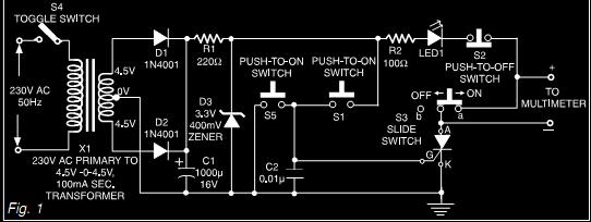
This document describes a simple triac tester circuit that can also be utilized for testing silicon-controlled rectifiers (SCRs) and both PNP and NPN transistors. The circuit operates on 3V DC, which can be derived from a Zener diode combined...
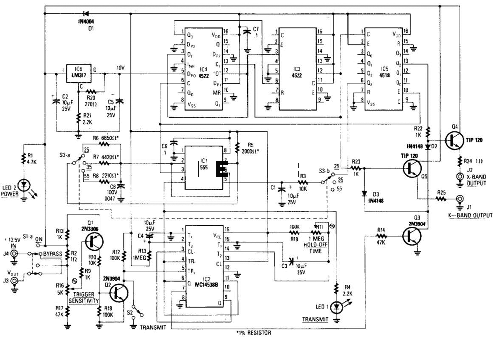
This circuit is a system designed to generate a pulsed modulation signal for a Gunn diode microwave oscillator. It features several preset speed settings (S3 a and b). A 555 timer is employed in conjunction with a frequency divider...
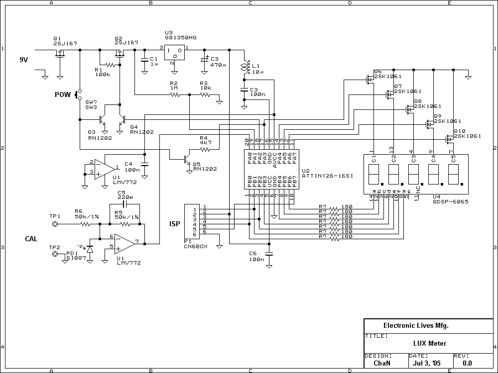
Lux meter circuit using an Atmel ATtiny26-16 microcontroller, which displays lux values on an LED display. The circuit utilizes 2SK1061 MOSFETs for driving the LEDs. The lux meter circuit operates by measuring ambient light levels and converting these measurements into...