
The MAX4104 4105 4304 4305 as the driving capacitive loads

The described circuit leverages the characteristics of the MAX4104/4105/4304/4305 operational amplifiers, which are designed for high-speed applications. These amplifiers can drive capacitive loads, but their performance can degrade significantly when the load exceeds specified limits. The capacitive load, when too high, can lead to instability in the feedback loop, resulting in undesirable oscillations.
To address this challenge, the isolation resistor RISO is strategically placed in series with the load. This resistor serves multiple purposes: it introduces a damping effect that reduces the Q-factor of the resonant circuit formed by the output capacitance and the load, thereby minimizing overshoot and ringing. The value of RISO needs to be carefully selected to balance the trade-off between stability and bandwidth. A higher resistance will improve stability but may reduce the bandwidth of the amplifier, while a lower resistance may enhance bandwidth but could lead to increased overshoot.
The overall design should also consider the characteristics of the load being driven. The load could be a capacitive sensor, an ADC input, or any other application where high-speed signal integrity is paramount. The circuit must ensure that the output voltage levels remain within the specified limits while maintaining signal fidelity.
In summary, the implementation of an isolation resistor in conjunction with the MAX4104/4105/4304/4305 operational amplifiers is crucial for achieving stable operation when driving capacitive loads. Proper selection of RISO is essential to optimize performance, ensuring that the circuit functions effectively without introducing unwanted artifacts such as overshoot or ringing. As shown in FIG grounds MAX4104/4105/4304/4305 using the capacitive load driving circuit isolation resistor RISO constructed. MAX4104/4105/4304/4305 the maximum permissible cap acitive load respectively 10pF, more than likely to overshoot and ringing oscillation. The circuit between the output terminals and the load plus an isolation resistor RISO, for suppressing overshoot ringing and ringing.
Related Circuits
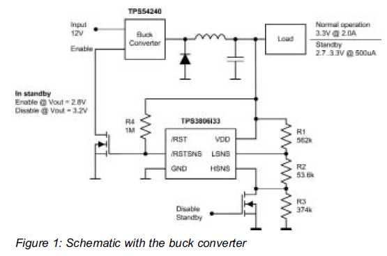
Small additional circuitry during standby can significantly enhance efficiency. In a modern vehicle, multiple microcontrollers are required to support safety, navigation, entertainment, and comfort electronics. The integration of additional circuitry during standby mode in automotive applications is crucial for optimizing...
Capacitive touch sensors operate based on the electrical capacitance associated with the human body. When a finger approaches the sensor, it establishes a capacitance to the ground, typically ranging from 30 to 100 pF. This phenomenon can be utilized...

An NPN bipolar transistor is typically utilized for relay switching, particularly with 12V coil-rated relays, as it helps maintain circuit separation. A diode is also added to prevent issues. The necessity of driving the relay with a transistor depends...
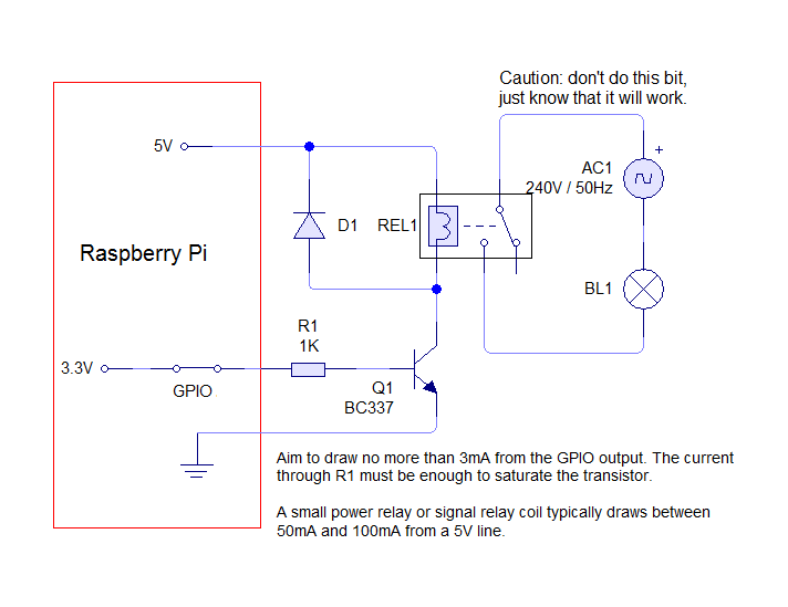
The circuit requires only four components, with a total cost of approximately 70 pence, making it an ideal candidate for classroom exercises. A low-cost relay, such as the Omron G5LA-1 5DC, can switch loads up to 10A at 240V....
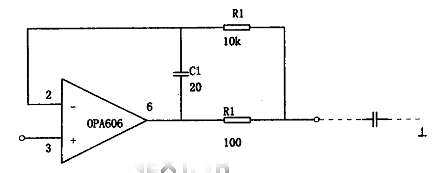
The isolation buffer circuit for capacitive loads is illustrated. When using an external operational amplifier (op-amp) with capacitive loads, the stability of the circuit is significantly affected, which leads to a degradation in dynamic performance. The circuit effectively demonstrates...
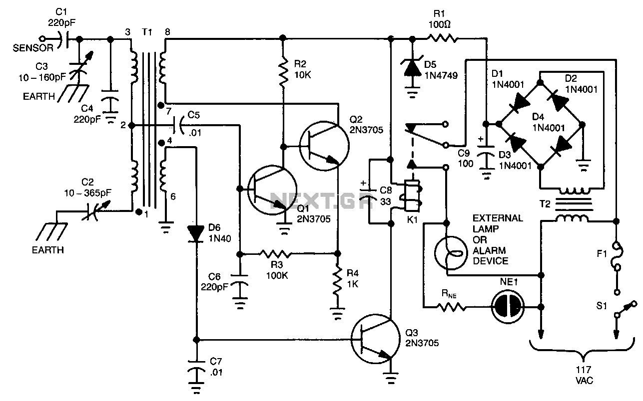
The unit is built around a balanced-bridge circuit that utilizes both capacitance and inductance. The bridge comprises capacitors C2 and C3, along with the center-tapped winding of transformer Tl. One end of the bridge is connected to ground through...