
microcontroller driving relay

An NPN bipolar transistor is a suitable choice for controlling a relay with a 12V coil, as it allows for isolation between the control circuit and the relay, ensuring that any noise or voltage spikes from the relay do not affect the control circuitry. When designing such a circuit, it is crucial to consider the coil resistance of the relay. For instance, with a coil resistance of approximately 125 ohms, the current drawn can be calculated using Ohm's law (I = V/R). In this case, the relay would require about 96mA (12V / 125Ω), which exceeds the maximum current that a microcontroller pin can safely supply. Therefore, utilizing a transistor to switch the relay is advisable.
The transistor should be connected in such a way that its collector is connected to one terminal of the relay coil, while the other terminal is connected to the positive supply voltage (12V). The emitter of the transistor is connected to ground. The base of the transistor is driven by a microcontroller pin through a current-limiting resistor. The value of this resistor can be calculated based on the desired base current, which should be sufficient to saturate the transistor when the relay is activated.
To ensure reliable operation, a diode must be placed in parallel with the relay coil, oriented to allow current to flow only when the relay is de-energized. This diode serves as a back EMF protection diode, preventing voltage spikes generated by the collapsing magnetic field of the relay coil from damaging the transistor or the microcontroller.
In scenarios where the supply voltage is higher than what the relay coil can handle, a series resistor (e.g., 100 ohms) may be necessary to limit the current through the coil to a safe level. However, this should be calculated carefully to avoid under-driving the relay. The overall schematic should clearly depict these connections, ensuring that all components are rated appropriately for the voltages and currents involved.I usually use an NPN Bipolar transistor to do the relay switching, mainly because my relays are 12v coil rated, but it also keeps everything nice and seperated. and yes i add a diode. with no problem. ( do I or did I need to drive it with a transistor ) but it seam like radio shack is getting out of the parts business.
I`ve got to place a order wit h digikey and though I mite find something better and cheaper. If you know the coil resistance it`s easy to calculate if you need a transistor. If it`s too low (say 125 ©) then you can use two pins to provide 40mA. Make sure you connect between the pins and 5V as the pins can sink more than source. The 100R series resistor is only required if the supply voltage is too high for the coil. The schematic also lacks the all-important back EMF protection diode. 🔗 External reference
Related Circuits
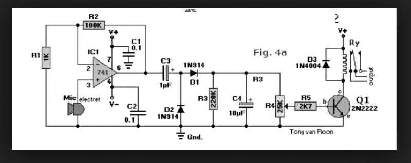
A circuit that enables control of a relay in response to sound from a non-amplified sound source, such as a computer, CD player, or a Digital Sound Recorder board. This circuit accepts audio input from any non-amplified sound source,...
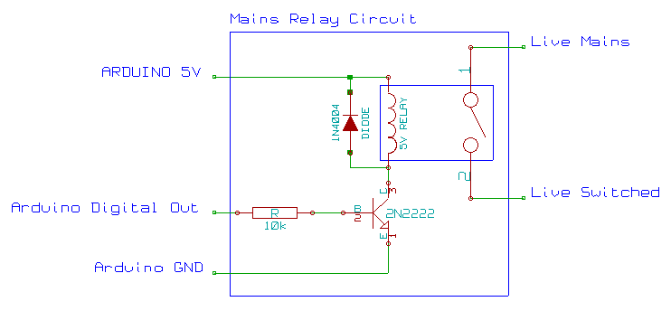
This mains AC relay module utilizes 5V relays that can be powered directly from an Arduino and can switch 230V. A basic energy monitoring and control system has been constructed using an Arduino 2009, off-the-shelf wireless remote control sockets,...

The relay power in the linear circuit is derived from a -120 V bias supply, while the transmit keying output from the Kenwood device is +12 V with a maximum current of 10 mA. A critical component of this...
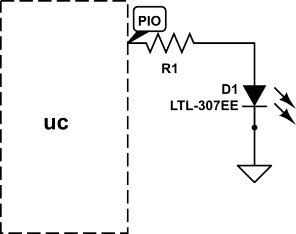
The LED will illuminate when the PIO (Programmable Input/Output) pin goes low, functioning similarly to a ground connection. In this configuration, the current is sourced from the power supply rather than the PIO, as in the first method. It...
A practical and engaging project involving a flip-flop relay circuit utilizing a 555 integrated circuit (IC). This circuit will continuously toggle two relays on and off in succession. The flip-flop relay circuit using a 555 IC is designed to alternate...

This circuit diagram represents a voice-operated relay. It functions similarly to a sound-activated switch circuit, which toggles the switch on and off (connects and disconnects) based on sound input. The output switch of this circuit is AC. The voice-operated relay...