
12V Speed Controller/Dimmer

This circuit operates on the principle of pulse width modulation (PWM), which effectively controls the average power delivered to the load by varying the duty cycle of the signal. The 7555 timer IC is configured in astable mode, generating a continuous square wave signal with a frequency of approximately 210Hz. The duty cycle of this waveform can be adjusted by varying the resistance and capacitance in the timing circuit, allowing for precise control over the motor speed or lamp brightness.
The output from the 7555 timer is fed into a pair of transistors (Q1 and Q2), which act as a signal amplifier and level shifter to drive the MOSFET (Q3). The MOSFET is responsible for switching the load on and off rapidly, which effectively reduces the average power supplied to the motor or lamp. The choice of a MOSFET for this application is crucial due to its high efficiency and ability to handle significant current loads without generating excessive heat.
Overall, this circuit design is straightforward, making it accessible for hobbyists and engineers looking for an economical solution for controlling 12V devices. Its applications are diverse, extending to automotive, marine, and recreational vehicle environments, as well as model building and DIY electronics projects. The simplicity of the design, combined with its effectiveness, makes it a valuable addition to any electronics toolkit.This handy circuit can be used as a speed controller for a 12V motor rated up to 5A (continuous) or as a dimmer for a 12V halogen or standard incandescent lamp rated up to 50W. It varies the power to the load (motor or lamp) using pulse width modulation (PWM) at a pulse frequency of around 220Hz.
SILICON CHIP has produced a number of DC speed cont rollers over the years, the most recent being our high-power 24V 40A design featured in the March & April 2008 issues. Another very popular design is our 12V/24V 20A design featured in the June 1997 issue and we have also featured a number of reversible 12V designs.
For many applications though, most of these designs are over-kill and a much simpler circuit will suffice. Which is why we are presenting this basic design which uses a 7555 timer IC, a Mosfet and not much else.
Being a simple design, it does not monitor motor back-EMF to provide improved speed regulation and nor does it have any fancy overload protection apart from a fuse. However, it is a very efficient circuit and the kit cost is quite low. There are many applications for this circuit which will all be based on 12V motors, fans or lamps. You can use it in cars, boats, and recreational vehicles, in model boats and model railways and so on.
Want to control a 12V fan in a car, caravan or computer This circuit will do it for you. The circuit uses a 7555 timer (IC1) to generate variable width pulses at about 210Hz. This drives Mosfet Q3 (via transistors Q1 & Q2) to control the speed of a motor or to dim an incandescent lamp. While the circuit can dim 12V halogen lamps, we should point out that dimming halogen lamps is very wasteful.
In situations where you need dimmable 12V lamps, you will be much better off substituting 12V LED lamps which are now readily available in standard bayonet, miniature Edison screw (MES) and MR16 halogen bases. Not only are these LED replacement lamps much more efficient than halogen lamps, they do not get anywhere near as hot and will also last a great deal longer.
Be the first of your friends to get free diy electronics projects, circuits diagrams, hacks, mods, gadgets & gizmo automatically each time we publish. Your email address & privacy are safe with us ! 🔗 External reference
Related Circuits
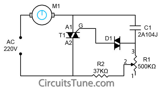
This is a simple ceiling fan regulator circuit diagram used to control the speed of a ceiling fan. In other words, it is an AC motor speed controller circuit that regulates the speed of an AC motor (ceiling fan)....
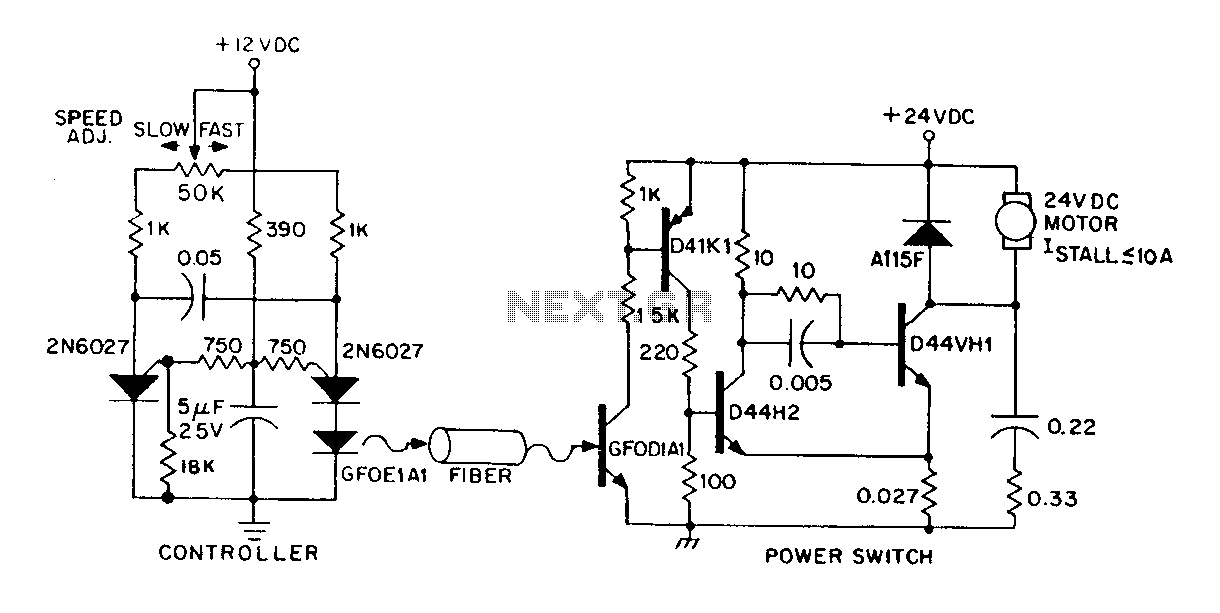
A DC power supply can be controlled through an optical fiber. The circuit includes a small DC motor (1/12 hp) that offers an isolated speed control channel. The control logic operates as an independent module, consuming 300 mW of...
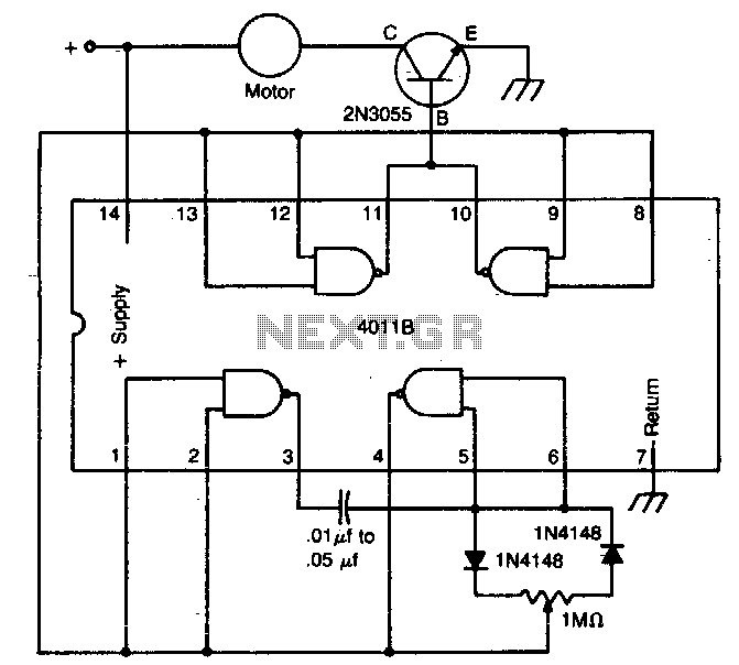
The circuit utilizes a 4011 CMOS NAND gate, a pair of diodes, and an NPN power transistor to create a variable duty-cycle DC source. By adjusting the speed control, the average voltage applied to the motor can be varied,...
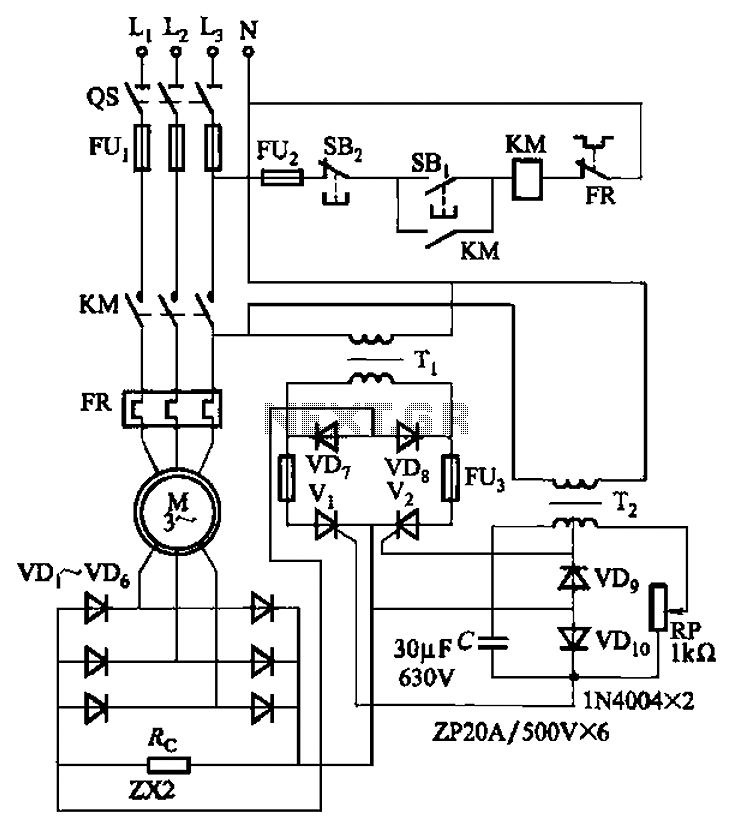
The circuit depicted in Figure 3-171 includes an auxiliary power supply that operates on single-phase AC power. It features a single-phase half-wave controlled bridge composed of diodes VD7, VD8, and thyristors V1, V2. The output current is managed by...
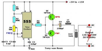
The 555 timer outputs a signal that is amplified by transistors Q1 and Q2 and fed into transformer T1, which is configured as a reverse-connected filament transformer with the appropriate step-up turns ratio. Capacitor C4 and inductor L1 serve...
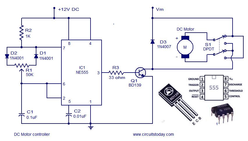
A DC motor controller based on an NE555 timer is presented here. The direction of rotation of the DC motor can also be changed using this DC motor speed control circuit. The described circuit utilizes the NE555 timer IC in...