
?» The stepper motor driver Creative Works of Tom McGuire

This circuit is suitable for driving 5 or 6 wire unipolar stepper motors, which are commonly used in various applications requiring precise control of position and speed. The design accommodates a voltage supply range from 9V to 24V, offering flexibility for different motor specifications.
The breadboard layout allows for easy prototyping and testing, while the option for a PCB layout caters to users looking for a more robust and permanent solution. For applications requiring multiple motors, such as in CNC machines or 3D printers, three identical circuits can be implemented to control the X, Y, and Z axes, ensuring synchronized movement.
In terms of motor performance, the example calculation provided demonstrates how to determine the appropriate wattage for the motor based on its voltage rating and resistance. This is crucial for selecting the correct load for the circuit. By using a bulb rated at approximately 6 watts, the circuit can simulate the motor load, allowing for effective testing and adjustment before connecting the actual motor. The recommendation to use a 24V power supply ensures that the motor operates efficiently, leveraging the full potential of its design.
Overall, this circuit design is practical for hobbyists and professionals alike, offering versatility in motor control applications while facilitating straightforward assembly and testing.This is designed to work with a varity of stepper motors, 5 or 6 wire unipolar types. Its also made to operate from about 9 volts to up to about 24 volts. Below is a bread board layout of the circuit but I can offer a PC board layout for those of you who want something a little more professional. You will need 3 of these for the X, Y, and Z motors . Onenice thing about this circuit is if you have a motor that is rated for 12 volts and has a resistance of 24 ohms then calculate the wattage of the motor like so: 12 * ( 12/24 ) = 6 Watts. Then put something close to a 6 watt bulb in the socket. Then use a 24 volt ( 12 * 2 ) power supply to run the circuit. It`s an easy way to get a more or less optimum preformance out of the motor. 🔗 External reference
Related Circuits
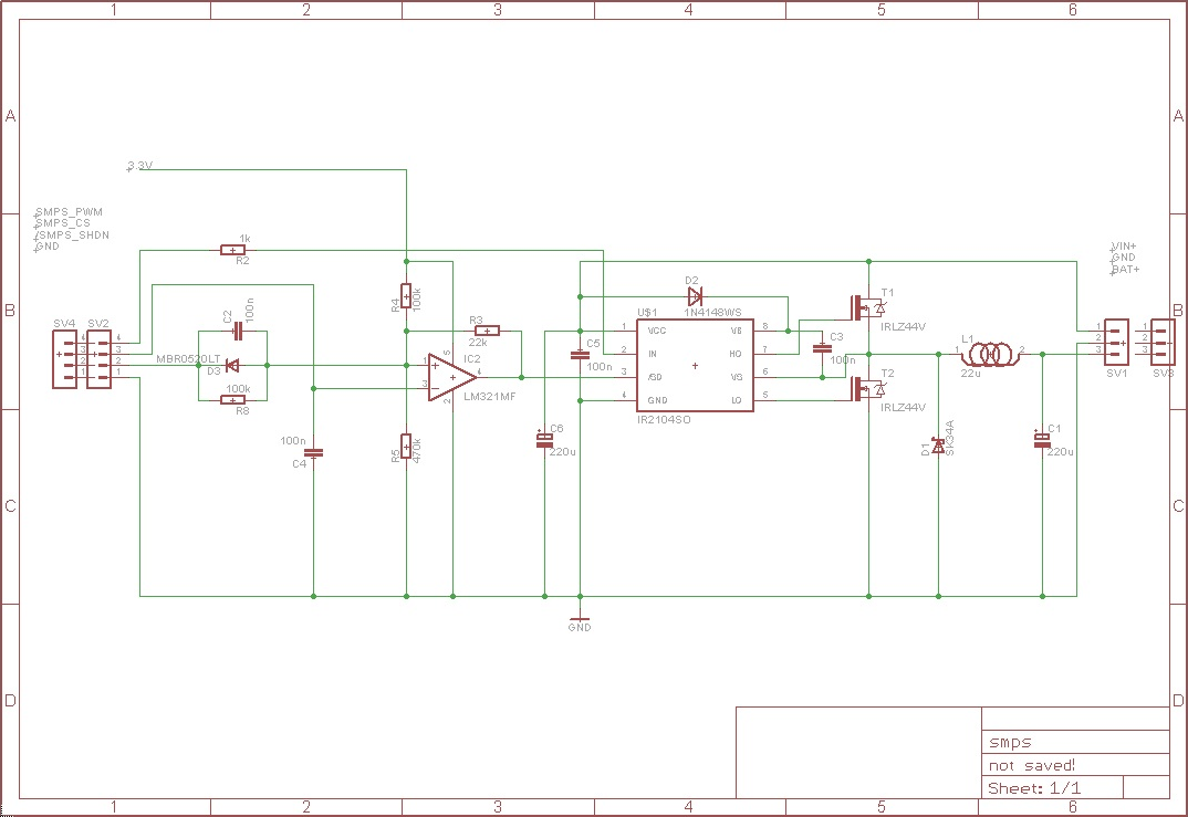
The circuit receives an input voltage (Vin), which is processed through a Switch Mode Power Supply (SMPS) utilizing two MOSFETs driven by an IR2104 driver. The output is directed to the battery positive terminal (Bat+). An LM321 operates as...
This circuit automatically activates a night lamp when the bedroom light is turned off. The lamp stays illuminated until the light sensor detects daylight in the morning. A super-bright white LED is utilized as the night lamp, providing bright...

An LCD (liquid crystal display) is an electronically modulated optical device composed of multiple pixels filled with liquid crystals, arranged in front of a light source (backlight) or reflector to create images in color or monochrome. The block diagram...

The figure illustrates a circuit involving dark tomb electric locks, specifically the fti: al: 4046B and XOR gate as the primary control mechanism. It emits pulses and utilizes silicon for successive pulse generation. The circuit operates with a normal...
Continuous wave (CW) operation is achievable with a current of up to 350 mA from a supply voltage range of 2 to 6 V. The system supports TTL modulation frequencies of up to 10 kHz, with an adjustable duty...
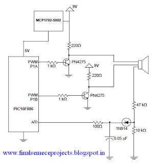
A horn driver project developed by Microchip Technology is illustrated in this circuit diagram. This horn driver project utilizes the PIC16F886 microcontroller from Microchip. The circuit diagram for the PIC microcontroller horn driver is straightforward and requires minimal external...