
Rapid control circuit of a stepping motor

The circuit described employs a combination of the 4046B phase-locked loop (PLL) and an XOR gate to create a control mechanism for dark tomb electric locks. The 4046B serves as a voltage-controlled oscillator (VCO), generating a frequency output that can be adjusted based on the voltage applied. The XOR gate functions as a logic control element, determining the output based on the state of the input signals.
In the typical operation mode, when the button is in its normal NC position, it allows current to flow through the circuit. Upon pressing the button, a brief delay of approximately 0.5 seconds occurs before the VCO begins to oscillate. This delay is crucial for establishing a stable output frequency. The output from the VCO is then fed into the XOR gate, which produces a one-shot pulse that can be utilized to trigger further actions in the circuit.
The continuous pulse output from the VCO can be modulated to control the speed of a stepping motor. The frequency of the output pulse can be adjusted by varying the voltage input to the VCO, allowing for precise control over the motor's operation. The circuit is designed to handle a range of operational conditions, ensuring that the stepping motor can be accurately positioned based on the pulse frequency.
If the button is released within 0.5 seconds, the system is designed to stop the VCO and reset the output. This feature allows for precise control of the motor's position, as the pulse width and frequency can be finely tuned to achieve the desired operational speed. The design also incorporates components such as resistors and capacitors to stabilize the circuit and manage the timing of the VCO output.
Overall, this circuit configuration provides a robust solution for controlling electric locks with a focus on precision and reliability in motor operation. The integration of the 4046B and XOR gate facilitates a versatile control system that can be adapted for various applications requiring accurate timing and pulse generation.The figure shows that dark tomb electric locks, fti: al: 4046B and XOR f] as the main control circuit, called S emitted pulses and silicon successive pulses built 4 Shaanxi. His normal button J 'NC position where ci.q were treated Di. D fjt electricity, q Yi cut orange lock loop VCO, f: l for XOR gate output f | J low 'l Bu. After pressing the button F. Cl, C2 {} not by M, R charge, after a 0.5 second delay after vco work. 0 to 5 seconds before the vco start working within the loose dike button, since the state XOR gate (14) and the output pin goes r95 - one-shot pulse. If the button is pressed fI <JH asked Takeo had 0,5 subtle, DV co work, after which the output voltage of shaped into a continuous pulse, and then sail XOR gate output t ....
c9) foot BU n © charged up voltage to frequency vco linear increase Jj , difficulties of this circuit emits a continuous pulse meters more of the L, the wine container to VC0 division i rate rose fq saturation value. Thus, the operation speed of the stepping motor. In the debt load shift refers to the vicinity of a boring after Tacitus. Release the button, cl. Island immediately discharged. vco stop Ii / l-. With less than 0 5 seconds of pressing the button is pressed the speed of a single pulse deep Kera precise location.
R. C, so that the value of hemp saturated vco frequency prison, etc. f: 1b Machine maximum step rate.
Related Circuits
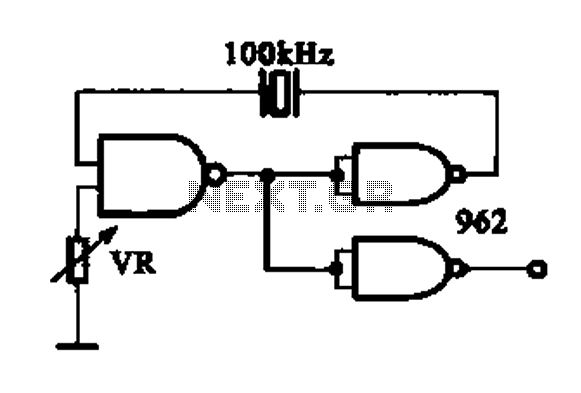
A DTL integrated circuit comprises a crystal oscillator, which is represented by the integrated circuits. The oscillation frequency ranges from 100 kHz to 1 MHz. Additionally, it includes a gate circuit that supplies a signal for the DTL oscillator...

The multi-purpose signal generator circuit consists of integrated circuit oscillators and frequency dividers. It generates square waves ranging from high frequencies to sub-audio frequencies and also produces a frequency standard in the VHF range. The alternative oscillator section feeds...
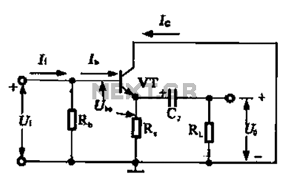
A common collector amplifier circuit can be analyzed through its DC and AC paths. The DC path provides a bias circuit for the power transistor, determining whether it is in an active or off state, primarily influenced by the...

The SD1143 transistor offers a gain of approximately 14 dB in this circuit. Its design takes advantage of the fact that a 175-MHz device exhibits significantly higher gain when operated at lower frequencies. The amplifier was initially intended for...
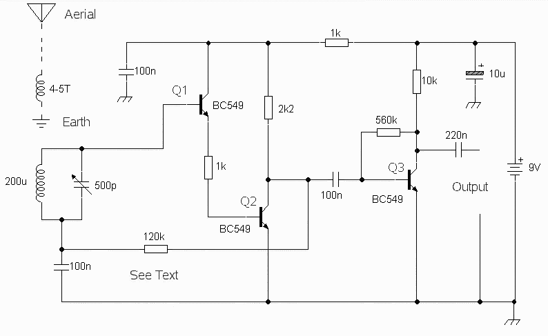
The circuit was designed to obtain signals through amplitude modulation, exhibiting good sensitivity and selectivity. Amplitude modulation. The amplitude modulation (AM) circuit is engineered to effectively capture and process radio frequency signals. The design focuses on achieving high sensitivity, allowing...
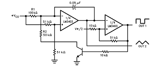
The LM3403 op-amp family includes the LM3303, which is a monolithic quad op-amp known for its high gain. It features a compensated internal frequency, allowing it to operate effectively across a wide range of voltages from both single and...