
Laser diode driver schematic

This circuit is designed to operate in continuous wave mode, providing a stable output current of up to 350 mA. The supply voltage can vary between 2 to 6 volts, making it suitable for various applications that require flexibility in power supply. The TTL modulation capability allows for modulation frequencies of up to 10 kHz, which is essential for applications in communications and signal processing where precise control of the signal is necessary.
The adjustable duty cycle feature enables users to modify the on-off ratio of the output signal, which is crucial for applications that require specific pulse widths. This capability can be particularly useful in applications such as PWM (Pulse Width Modulation) control for motors or other devices where varying the power level is needed.
The rapid soft start function ensures that the circuit initializes smoothly upon power-up, preventing sudden inrush currents that could potentially damage components or affect performance. This feature is beneficial in sensitive applications where stability is critical during the startup phase.
Power adjustments can be easily made through an external resistor, allowing for straightforward customization of the output power without the need for complex circuitry. This simplicity in design aids in reducing overall costs and improving the ease of integration into various electronic systems.
In summary, this circuit offers a versatile solution for applications requiring CW operation with adjustable power and modulation capabilities, while ensuring safe and efficient performance during startup and operation.CW operation up to 350mA from 2. 8. 6V supply voltage TTL modulation frequency up to 10KHz, with adjustable duty cycle. Rapid soft start after power-on. Simple power adjustment via the external resistor. 🔗 External reference
Related Circuits
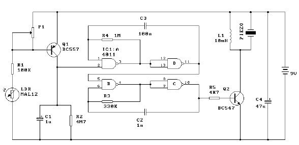
This light alarm schematic circuit is designed using common electronic components, as illustrated in the circuit diagram below. The light alarm circuit will activate an alarm as soon as the drawer is opened and light falls on the Darlington...
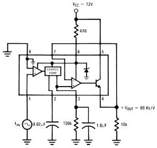
The LM2917 IC chip is specifically designed as a Frequency to Voltage Converter. It requires only a few external components for its operation. The datasheet for the LM2917 IC includes several application examples of the Frequency to Voltage Converter....
The circuit employs two Light Dependent Resistors (LDRs) arranged in series with a separation of approximately half a meter. This configuration allows each LDR to detect the presence of a person entering or exiting the room. The processed outputs...

The driving circuit depicted in Figure 18-12 consists of a connection between the driving portion, the microcontroller, and the air conditioning operation components of the bridge. The microcontroller's digital signal levels from ports P4.0 to P4.3 (approximately 12 feet)...
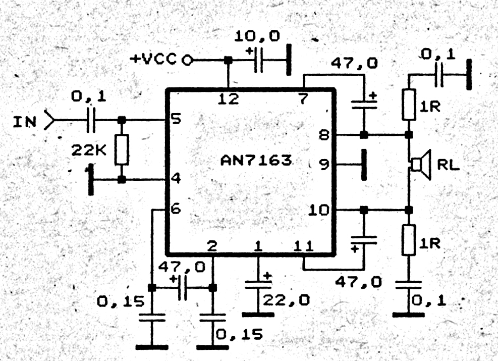
This 5.1 surround amplifier circuit schematic utilizes the IC AN7168 as the primary component. The circuit requires a minimum voltage of 12V and a maximum voltage of 24V, with a recommendation of 12V due to the voltage ratings of...
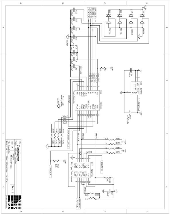
The following are detailed schematics for the QScreen Controller. The QScreen Controller integrates an embedded computer utilizing the 68HC11 microcontroller, along with a touch panel and an LCD (liquid crystal display) graphic user interface (GUI) that is well-suited for...