
led How should I build this circuit

To construct a parallel circuit utilizing a 3V blue LED with a maximum current rating of 0.03A, the following considerations and components are essential.
The USB power supply typically provides a voltage of 5V. To safely operate the LED, a current-limiting resistor must be included in the circuit to prevent excess current from damaging the LED. The resistor value can be calculated using Ohm's Law and the formula for a series circuit, which is:
\[ R = \frac{V_{supply} - V_{LED}}{I_{LED}} \]
Where:
- \( V_{supply} \) is the supply voltage (5V from USB),
- \( V_{LED} \) is the forward voltage drop of the LED (3V),
- \( I_{LED} \) is the forward current through the LED (0.03A).
Substituting the values:
\[ R = \frac{5V - 3V}{0.03A} = \frac{2V}{0.03A} \approx 66.67 \Omega \]
A standard resistor value of 68 Ohms can be used, as it is a common resistor value and will provide adequate protection for the LED.
In a parallel circuit configuration, multiple LEDs can be connected across the same voltage source, each with its own current-limiting resistor. This ensures that each LED receives the appropriate voltage and current. It is important to calculate the resistor for each LED independently, maintaining the same values as calculated above.
The schematic for this circuit will consist of:
1. A 5V USB power source.
2. Multiple blue LEDs, each rated at 3V and 0.03A.
3. Individual 68 Ohm resistors connected in series with each LED.
4. All LEDs and resistors connected in parallel to the power supply.
This configuration allows for the safe operation of the LEDs while maximizing the available current from the USB source. It is recommended to verify the connections and component ratings before powering the circuit to ensure proper functionality and prevent damage to the components.The LED is 3V, and according "to the internet" (there was no manufactorer info on it) a blue LED usually supports up to 0. 03A. Since I have spare current from the USB I thought I should build a parallel circuit. Now, the last class on circuits I had was on high school, so I don`t know if my calculations and schematics are correct:
🔗 External reference
Related Circuits
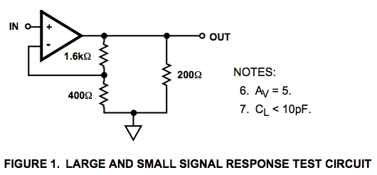
Here is a circuit diagram for a signal response test circuit from the specification sheet for a HA-5195 operational amplifier. It appears to be a non-inverting amplifier circuit with a gain of 5, along with a 200-ohm resistor connecting...
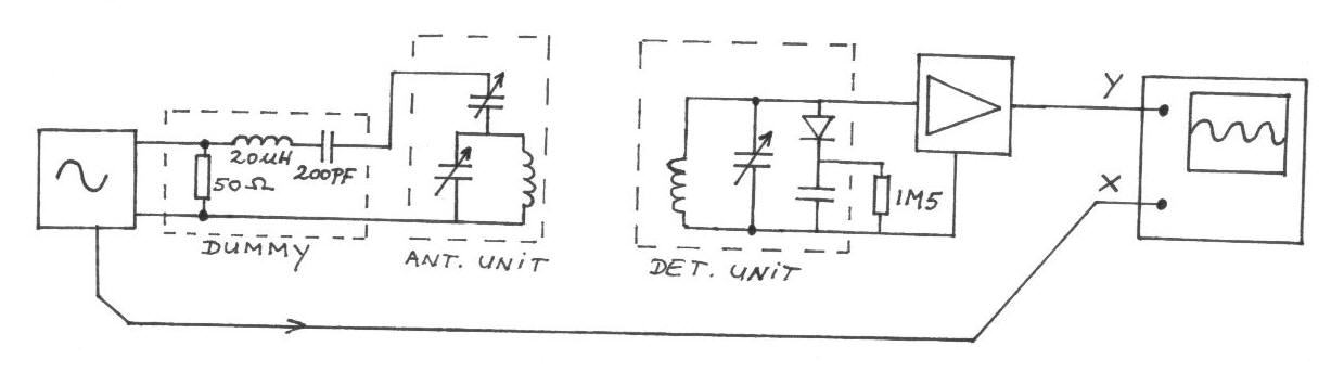
The frequency remains constant, oscillating between two predetermined values. On the oscilloscope display, a frequency spectrum is observed, showcasing the response curves of the two circuits. The input voltage of the receiver is 0.1 Volt peak-to-peak, while the voltage...
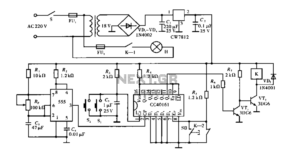
Corridor counter delay circuit for controlling lights. This circuit is tested and functional. When the circuit is energized, the 555 oscillator starts to oscillate. The CC40161 is cleared, and an integrating circuit composed of R3 and C5 transitions the...
The two circuits demonstrate the use of a 555 timer to activate a relay for a specified duration when a momentary normally open (N/O) push button is pressed. The circuit on the left is designed for extended time periods,...
Active power factor correction stabilizes the electrical demand of a device to provide optimal power factor characteristics for various types of loads. To comply with power factor regulations, a cost-effective solution should be designed. In many applications, the requirement...
Converting current into voltage is undesirable for two reasons: first, an impedance is inserted into the measuring line, causing an error; second, amplifier offset voltage is also amplified, leading to a subsequent loss of accuracy. The use of a...