
6 graphic equaliser circuit 741 op amp

The six-band graphic equalizer circuit utilizes the IC 741 operational amplifier to facilitate sound modification across designated frequency bands. Each of the six frequency bands corresponds to specific audible frequencies: 50Hz, 160Hz, 500Hz, 1.6kHz, 5kHz, and 16kHz. The circuit architecture allows for independent adjustment of each band through the use of 100kΩ linear potentiometers, enabling users to boost or cut the signal in each respective frequency range.
The operational amplifier configuration ensures that the circuit can effectively handle the necessary gain adjustments while maintaining audio fidelity. The circuit is designed to be powered by a supply voltage ranging from 6V to 20V, providing flexibility for integration with various audio systems, including amplifiers and preamplifiers. This adaptability allows the equalizer to be employed in multiple scenarios, from home audio systems to professional sound setups.
Power consumption is minimal, making the circuit efficient and suitable for continuous use without significant energy draw. The design emphasizes usability, allowing users to tailor their audio experience by modifying the frequency response to suit personal preferences or specific audio requirements. The overall circuit design is compact and can be easily incorporated into existing audio equipment, enhancing its functionality and performance.This circuit is half dozen Band Graphic Equaliser, you can modify sound in low, mid and high that circuit used IC 741 Op-Amp. With this circuit you can management and mix frequencies and tones as desired. The audiblefrequency spectrum is roofed in six steps: 50Hz, 160Hz, 500Hz, 1. 6kHz, 5kHz, 16kHz. All potentiometers are of 100k © linear kind. The circuit provides adequate boost / cut for traditional use. power provide for the circuit may be derived from the amplifier / preamplifier itself. The wide rangeof provide voltage (6V-20V) makes the circuit terribly versatile. Power consumption is negligible. 🔗 External reference
Related Circuits
This is a FET amplifier circuit that utilizes an FET transistor. The gate of the FET must be negative with respect to the source to achieve proper biasing. The voltage across the source resistor is generated by the drain...
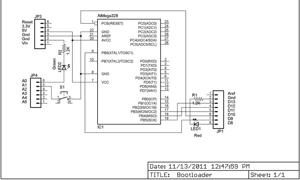
This Lazy Old Geek is also an Arduino enthusiast. One of the common microcontrollers used by Arduinos is the Atmega328 chip. To utilize Arduino software, the Atmega must be equipped with bootloader software. There is a notable difference between...
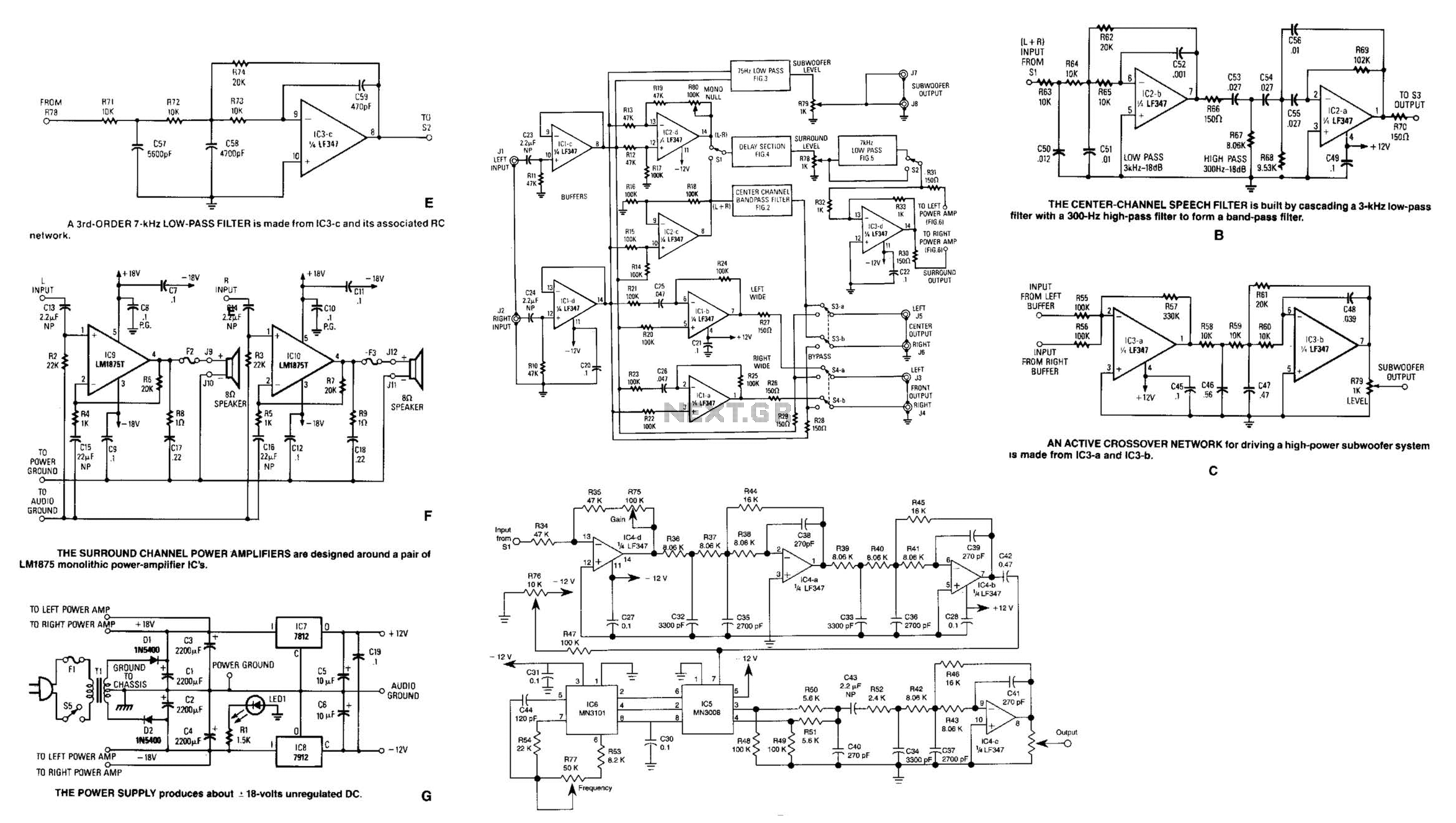
Referring to the simplified schematic in A, the audio frequency generator (AFG) consists of 10 relatively simple circuit elements. IC1-c and IC1-d are configured as unity-gain non-inverting buffer amplifiers. The summing amplifier, IC2-c, combines equal amounts of the left...
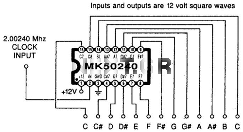
Using an MK50240, this circuit generates 12 top octave tones. The input and output lines can be separated using a binary divider IC to achieve the lower notes. Inputs and outputs are 12-volt square waves. The MK50240 is a specialized...

A capacitor step-down DC power supply circuit is presented. This circuit eliminates the need for power transformers, utilizing capacitive voltage drop rectification and regulation, which significantly reduces the overall size of the circuit. The circuit includes a capacitor step-down...
You will need to go to extremes with the heatsink (fan cooling is highly recommended). It was originally intended for "light" intermittent duty, suitable for an equalised subwoofer system (for example using the ELF principle - see the Project...