
The TRIAC

SCRs, or Silicon Controlled Rectifiers, are semiconductor devices that act as electronic switches. They are primarily used in applications where control of high power is required. The unidirectional nature of SCRs means that they can conduct current in only one direction, which is advantageous for DC circuit applications.
When two SCRs are arranged in a back-to-back parallel configuration, they can effectively manage bidirectional current flow, allowing for the control of AC signals. In this setup, one SCR will conduct during the positive half-cycle of the AC waveform, while the other SCR conducts during the negative half-cycle. This arrangement is particularly useful in applications such as phase control, where varying the power delivered to a load is necessary.
The gate terminal of each SCR is critical for triggering the device. By applying a small voltage to the gate, the SCR can be turned on, allowing current to flow from the anode to the cathode. Once triggered, the SCR remains in the conducting state until the current flowing through it drops below a certain threshold, known as the holding current.
In practical applications, SCRs are commonly found in motor speed controls, light dimmers, and power regulators. The ability to handle high voltage and current levels makes them suitable for industrial applications where reliable and efficient control of electrical power is essential.
Overall, the use of SCRs in electronic circuits provides significant advantages in terms of efficiency and control, particularly in systems that require the management of DC or AC power.SCRs are unidirectional (one-way) current devices, making them useful for controlling DC only. If two SCRs are joined in back-to-back parallel fashion .. 🔗 External reference
Related Circuits

This time delay switch circuit is designed to activate an AC load, such as lamps, after a delay of three minutes. It helps protect the load from inrush currents and transients during power-on, which can potentially harm the device....
Light Sensitive Staircase Switch with Triac. The operation of the third circuit is quite similar, except that it incorporates photo sensitivity. The circuit is illustrated in the schematic. When there is insufficient light... The light-sensitive staircase switch circuit utilizes a...
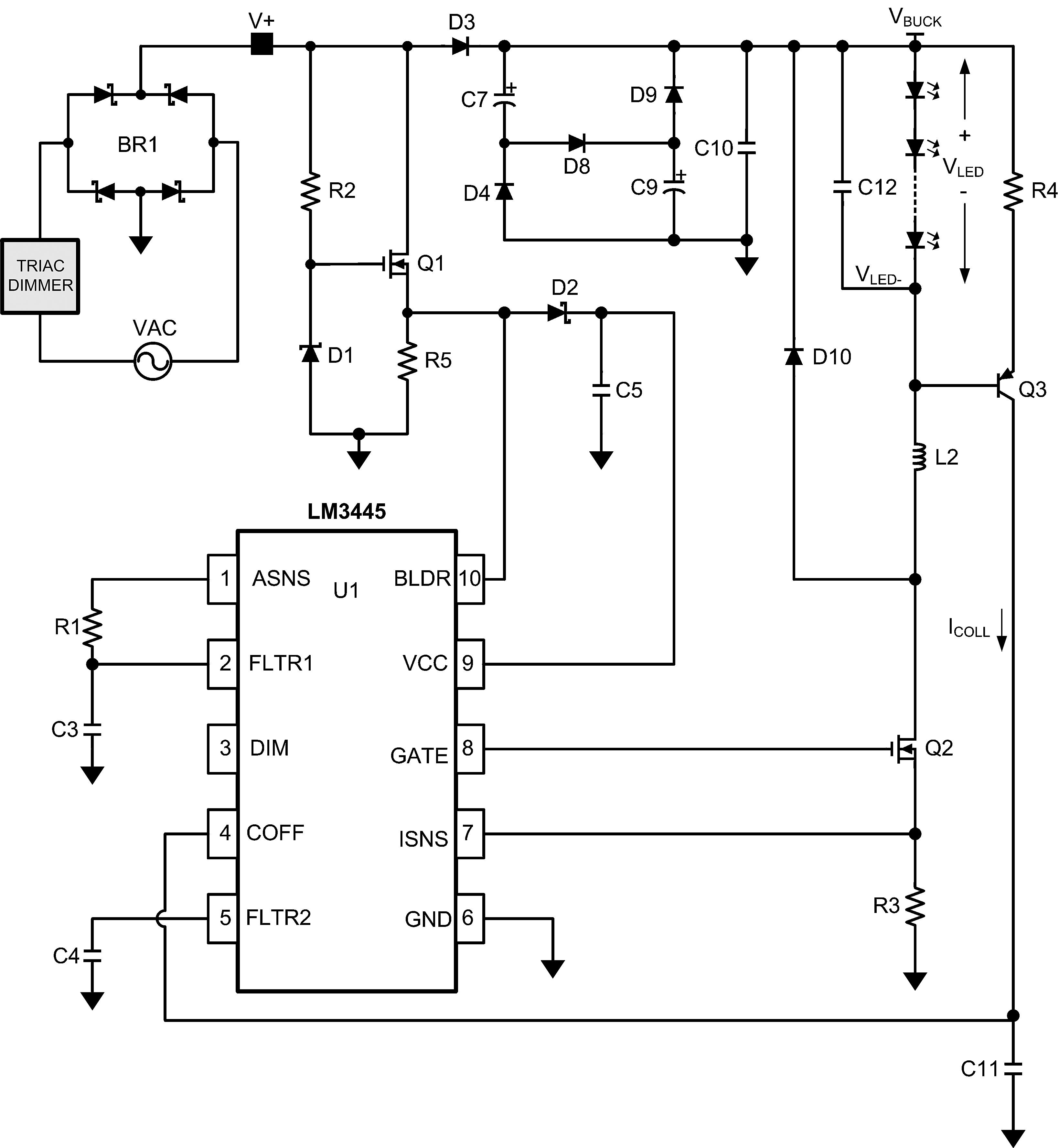
The LM3445 is an adaptive constant off-time AC/DC buck (step-down) constant current controller designed for compatibility with triac dimmers. The LM3445 is a specialized integrated circuit that functions as a constant current controller in AC/DC applications, particularly suited for LED...
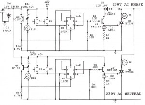
The task involves converting a relay in a design to a triac. The circuit switches a 120V nichrome wire with a resistance of 60 ohms. The circuit is powered by a 12V transformer, and there is a 120V neutral...
A very simple dimmer circuit with only the essentials. In this circuit, the values are given for a BT138 at 220V AC. For 115V AC, experimentation with values may be necessary. R1 can vary from one triac to another;...
The series of light switches is slightly different from traditional designs. These light switches can operate directly on the AC power network. The main components of the circuit include a TRIAC and a Light Dependent Resistor (LDR). The circuit...