
The Ultimate Audio Filter
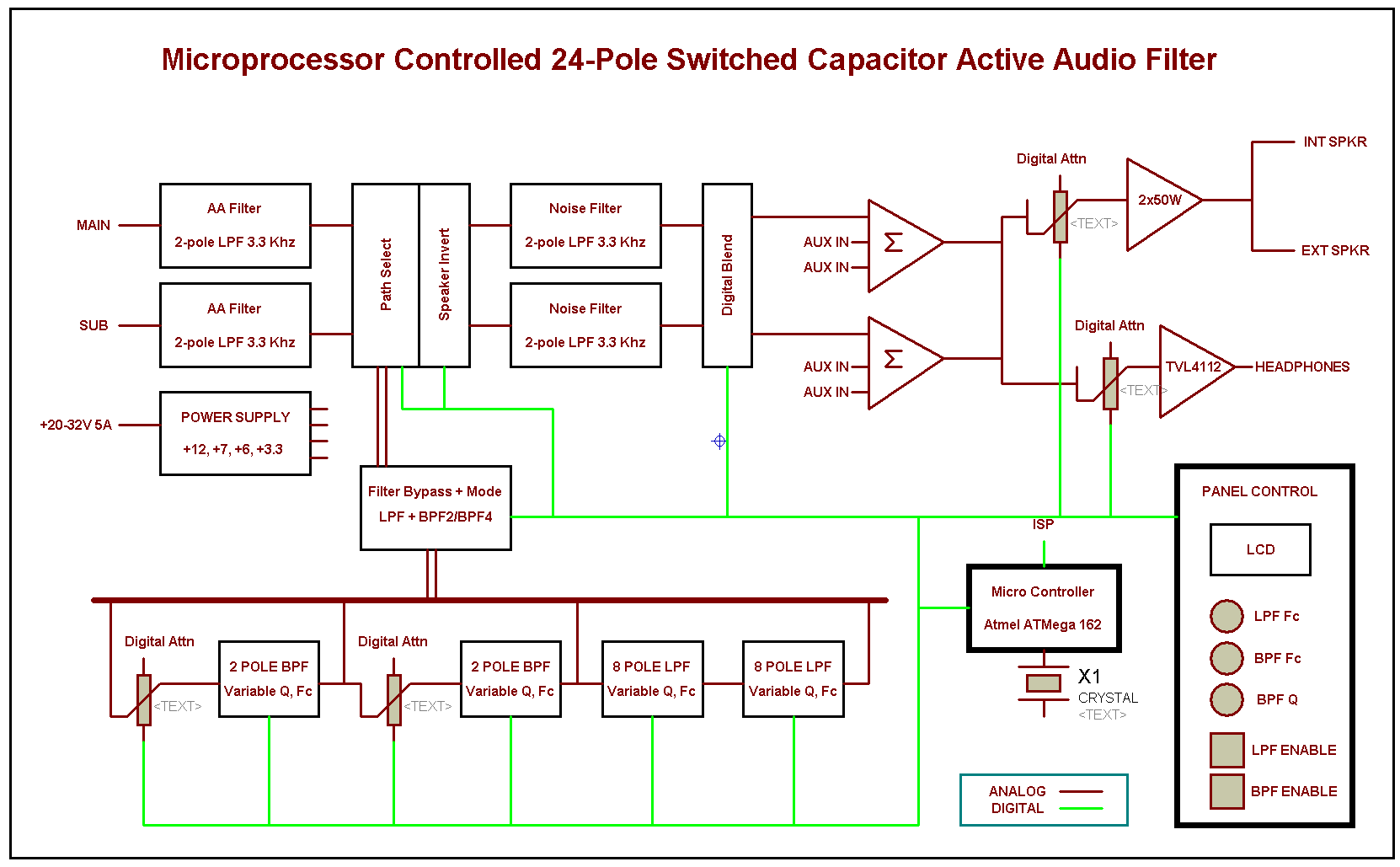
In addition, the ringing performance of the DSP can be better than the analog variety at the expense of higher demands on DSP hardware. If any active filter project can be called a Beast, it`s possibly this one. Based on the Maxim MAX262 universal 4-pole switched capacitor filter (SCF) to provide the BPF function.
That is followed by a pair of MAX7400 8-pole elliptical response LPF modules. These filters are adjustable for performance like cutoff frequency and (in the BPF filter case) Q. Total pole count here is 24. In addition, fixed LPFs on the input, output and amplification modules add an additional 6 poles of noise rejection roll off. 15 IC total. The design objectives were to allow for maximum flexibility of settings. The disadvantage of traditional fixed active filters are that their performance is not adjustable. Yet often times, band conditions would allow for a different Q or center frequency setting and with a fixed filter, that is not possible.
The low end filtering was not considered because the 1K-mod combined with the IF shift on the 2nd RX allows for the similar steep roll-off on an adjustable basis. In addition, the impact of the group delay (which is realized as ringing) is much harder to address in the active AF filter.
So low end roll off was gradual and just enough to help ensure some attenuation of possible 60 hz hum. Here, thanks to the Maxim Switched Capacitor Filter (SCF) ICs, a micro-controller (Atmel AVR running at 11.
125 MHz) provides the ultimate in flexibility. It drives an LCD display allowing for convenient indication of the filter settings. The two BPF filter modules within the MAX262 are individually programmable and with separate clocking to set the center frequency of the following LPF elliptical as well. As a result, an infinite variety of BPF filter response implementations are possible - all adjustable by firmware.
The LPF is only adjustable at the cutoff frequency - however, by changing the socketed LPF filter IC, bessel, butterworth, elliptical R1. 2 or elliptical R1. 5 variations are possible. At the input of the signal chain are AA filters. The sample frequency of the filter is about 100x the signal frequency so anti-alias filtering is not needed.
However, I wanted to keep the high frequency noise out of the signal path at the start. The AA filters are a low Q butterworth design and provide about 12db of gain in the process. The reason for the gain is that the noise floor of the SCF is fixed - so by pushing the signal strength up prior to these stages, the SNR is increased. The gain of the BPF modules is equal to the Q. Which means in the case of a Q=8 (as the APF filter design would require), an input signal of 1V would require an output swing of 8V.
The filters are fed with a 6V signal to maintain logic compatibility with the MCU and that would mean clipping - certainly a bad thing. To avoid saturation of the BPF output under high Q conditions, digital pots prior to each stage allow for a preemptive gain reduction keeping peak voltage swings in check.
Two additional digital pots prior to each output path (to the speaker amp and headphone amps) allow for individual gain setting. and leveling regardless of the headphone or speakers used. Following the SCF BPF/LPF modules are the noise filters - these are low Q unity gain LPF 2-pole stages which buffer the 10K output of the SCF and drive the digital blend circuit.
The noise filters ensure there are no SCF noise artifacts present in the signal and the low Z output ensures the rest of the circuit sees a consistent supply Z. The digital blend circuit allows mixing of the channel 1 and channel 2 inputs if the operator were to prefer not to have a one channel per ear operation method.
Each signal path has it`s own blend control, so for example, the main can be shared while the sub can remain isolated. The amount of blend is adjustable from 0 (isolated) to 100% (sound levels equal from both speakers). 🔗 External reference
Related Circuits
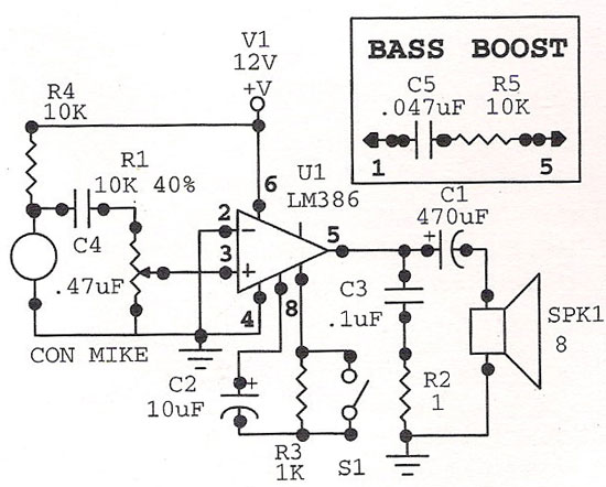
The LM386 Audio Amplifier is one of the earliest audio integrated circuits (ICs) and remains widely used. It operates with a minimal number of external components and is essential for general hobby circuits. The LM386 is a low-voltage audio power...
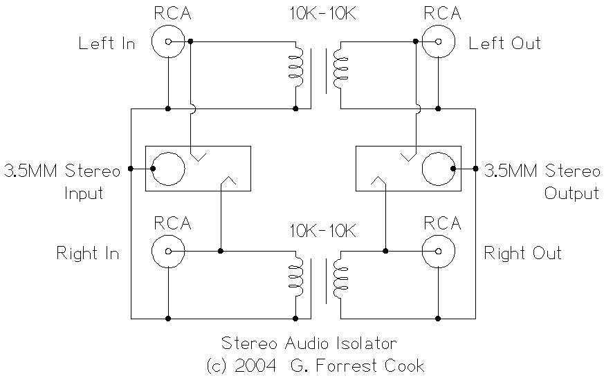
This circuit is useful for removing ground loop hum on a remote line level audio signal line. It can be used to connect a computer sound card to a stereo amplifier's line input. Other uses include tapping into a...
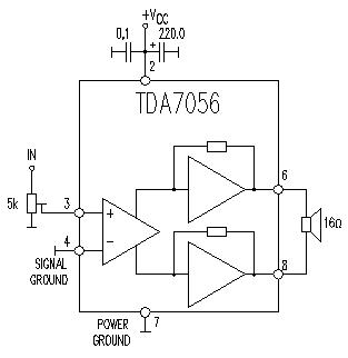
This TDA7056 power audio amplifier circuit diagram project is designed to deliver a maximum output power of 1 watt into an 8-ohm load when powered by a 6-volt supply, or a maximum output power of 3 watts into a...
This circuit illustrates a Car Radio Audio Amplifier using the TDA2003 integrated circuit. The datasheet for the TDA2003 includes electrical characteristics and schematic wiring details. The TDA2003 is a high-performance audio amplifier designed for automotive applications. It is capable of...
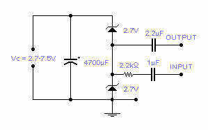
Two low voltage, low power zeners are used to control electronically the level of an audio signal. The attenuation range is from 6 to 58dB for an input current from 0.042 to 77 mA corresponding to a control voltage...
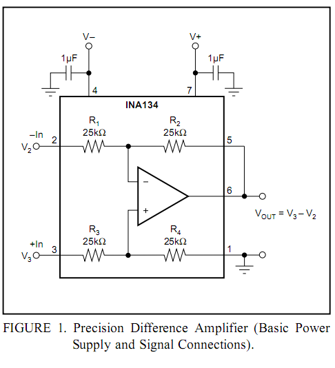
Burr-Brown DRV134 audio balanced line receiver schematic PCB/kit available? There is an interest in creating a balanced line receiver using the DRV134. The Burr-Brown DRV134 is an integrated circuit designed for audio applications, specifically for converting unbalanced audio signals...
Warning: include(partials/cookie-banner.php): Failed to open stream: Permission denied in /var/www/html/nextgr/view-circuit.php on line 713
Warning: include(): Failed opening 'partials/cookie-banner.php' for inclusion (include_path='.:/usr/share/php') in /var/www/html/nextgr/view-circuit.php on line 713