
The use of FR-FG and FR-AL achieve multiple synchronous motor running circuit
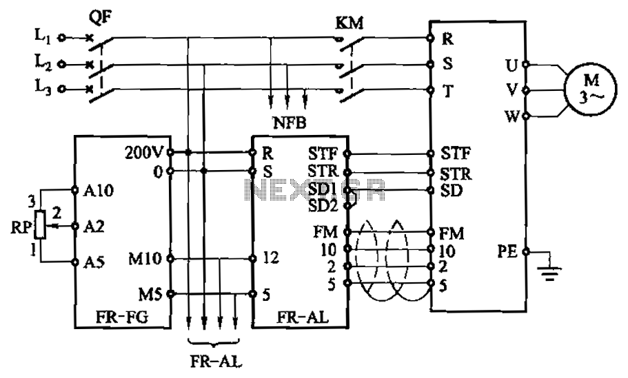
The described circuit facilitates the synchronous operation of multiple motors using the Mitsubishi inverter's FR-FG and FR-AL boxes. The FR-FG serves as the primary speed controller, allowing for real-time adjustments to the main motor's rotation speed. This is crucial in applications where precise synchronization between multiple motors is required, such as in conveyor systems, robotic arms, or multi-axis machining tools.
The FR-AL linkage setting operation box complements the FR-FG by providing a means to link the speed settings of additional motors to the primary motor. This ensures that any adjustments made to the primary motor's speed are automatically reflected in the operation of the secondary motors, maintaining a consistent operational speed across all units.
The circuit typically includes feedback mechanisms to monitor the speed of each motor, ensuring that they remain synchronized even under varying load conditions. This can be accomplished using tachometers or encoders that provide real-time feedback to the inverter system. Additionally, safety features should be integrated into the circuit design to prevent overloading and ensure reliable operation.
In summary, the integration of the FR-FG and FR-AL boxes in the circuit design allows for efficient and synchronized control of multiple motors, enhancing operational efficiency and reliability in various industrial applications. By the main speed setting box FR-FG and the linkage setting operation box FR-AL (Mitsubishi inverter) multi motors synchronous operation. Circuit is shown. Using these two exte rnal units, you can easily adjust the speed of the primary (main motor rotation speed), and the rest of the motor speed speed consistent with this.
Related Circuits
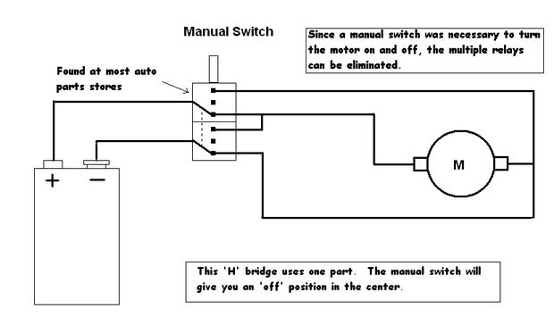
Control a toy car. The toy car is operated via a wired controller, rather than being radio-controlled. The intention is to utilize relays to control the toy through a parallel port. There are various types and models of relays,...
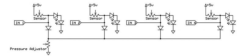
A dance pad consists of four pressure sensors (up, down, left, right). A USB controller has already been created for the dance pad, and the next step involves connecting the actual sensors. The intention is to pull the input...
The only drawback of a single operational amplifier (op-amp) stage is that it inverts the signal, necessitating an additional inverting buffer to restore the original phase if absolute phase is a concern. Various schematics exist for both configurations, but...
The inductor is made by winding 8 turns of #24 insulated solid copper wire on a 5 mm screwdriver. I used a conductor from a piece of category 5 quad twisted pair, left over from wiring the house with...
This simple alarm timer circuit is constructed using a 4060 integrated circuit, which features a stable oscillator with a relatively wide frequency range. The alarm timer circuit utilizes the CD4060 IC, which combines a low-frequency oscillator and a binary counter....
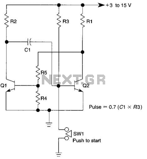
This circuit is activated when switch SW1 is pressed, grounding the base of transistor Q2. The pulse rate is approximately equal to 0.7 multiplied by the product of resistor R3 and capacitor C1. The described circuit features a transistor Q2,...
Warning: include(partials/cookie-banner.php): Failed to open stream: Permission denied in /var/www/html/nextgr/view-circuit.php on line 713
Warning: include(): Failed opening 'partials/cookie-banner.php' for inclusion (include_path='.:/usr/share/php') in /var/www/html/nextgr/view-circuit.php on line 713