
Thermally based anemometer

This action raises Al's negative input potential, leading to a decrease in Ql's emitter voltage until the circuit stabilizes at an operating point. To maintain balance in the bridge, Al adjusts to keep the lamp's resistance, and consequently its temperature, constant. The bridge values of 20 kΩ and 2 kΩ have been selected to ensure the lamp operates just below the incandescence threshold. To use this circuit, position the lamp in the airflow such that its filament is at a 90° angle to the flow. First, either stop the airflow or shield the lamp from it, and then adjust the zero-flow potentiometer to achieve a circuit output of 0 V. Next, expose the lamp to an airflow of 1000 feet per minute and calibrate the full-flow potentiometer for a 10 V output. These adjustments should be repeated until both calibration points are accurately set. Once this procedure is completed, the airflow meter can measure accurately within 3% across the entire range of 0 to 1000 feet per minute.
The circuit utilizes a modified type 328 lamp as a sensor, which is effective due to its positive temperature coefficient. The operational amplifier (Al) plays a crucial role in monitoring the bridge circuit and adjusting the feedback to maintain a constant temperature of the lamp. The transistor (Ql) amplifies the current output from Al, ensuring that the bridge circuit remains balanced during operation. The selected resistor values are critical in setting the operational parameters of the circuit, allowing it to function effectively just below the incandescence point of the lamp.
For practical implementation, the design requires careful calibration to ensure accuracy. The positioning of the lamp within the airflow is vital, as it must be oriented correctly to respond effectively to changes in flow rate. The zero-flow and full-flow potentiometers are essential for establishing the baseline and maximum output levels, respectively. This meticulous calibration process enables the airflow meter to deliver reliable and precise measurements, making it suitable for various applications in measuring air or gas flow rates in different environments.This design used to measure air or gas flow works by measuring the energy required to maintain a heated resistance wire at constant temperature. The positive temperature coefficient of a small lamp, in combination with its ready availability, makes it a good sensor.
A type 328 lamp is modified for this circuit by removing its glass envelope. The lamp is placed in a bridge which is monitored by Al. Al's output is current amplified by Ql and fed back to drive the bridge. When power is applied, the lamp is at a low resistance and Ql's emitter tries to come full on. As current flows through the lamp, its temperature quickly rises, forcing its resistance to increase. This action increases Al's negative input potential. Ql's emitter voltage decreases and the circuit finds a stable operating point. To keep the bridge balanced, Al acts to force the lamp's resistance, hence its temperature, constant. The 20 k - 2 k bridge values have been chosen so that the lamp operates just below the incandescence point.
To use this circuit, place the lamp in the air flow so that its filament is at a 90° angle to the flow. Next, either shut off the air flow or shield the lamp from it and adjust the zero flow potentiometer for a circuit output of 0 V.
Then, expose the lamp to air flow of 1000 feet/minute and trim the full flow potentiometer for 10 V output. Repeat these adjustments until both points are fixed. With this procedure completed, the air flowmeter is accurate within 3% over the entire 0-1000 foot/minute range.
Related Circuits
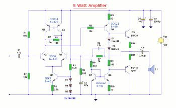
The diagram illustrates a 5W audio amplifier circuit constructed using power transistors BD139 and BD140 for the final amplification stage. This compact amplifier serves as a general-purpose amplifier suitable for applications such as computer audio, radio, MP3 players, and...
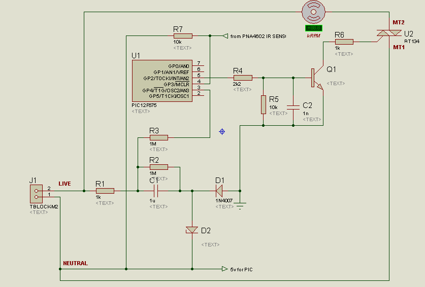
A project is underway to control the speed of an electric fan (220Vac, 60W, 5A max.) automatically using a microcontroller based on certain parameters. The circuit design for controlling the speed of an electric fan involves several key components to...
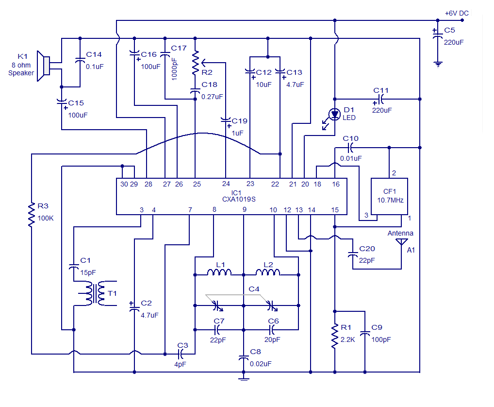
It is a high-quality FM receiver circuit based on the IC CXA1019. The CXA1019 is a monolithic silicon bipolar radio FM/AM receiver IC designed for Sony. The built-in circuitry within the CXA1019 includes an RF amplifier, mixer, oscillator, amplifier,...
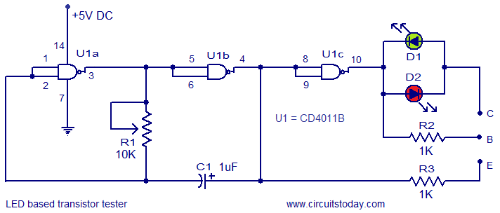
This circuit represents a simple transistor tester that utilizes two LEDs to indicate the condition of a transistor. It is capable of testing both PNP and NPN transistors. The core component of the circuit is the quad 2-input CMOS...
This ultrasonic anemometer is designed for the two-dimensional measurement of horizontal wind speed components and wind direction, as well as virtual temperature. Due to its high measurement rate, the device effectively captures gusts and peak values without delay. The...
The following circuit illustrates a stepper motor controller based on the PIC16F84A integrated circuit. It features a transistor used for driving the motor. The stepper motor controller circuit utilizes the PIC16F84A microcontroller, which is a popular choice for controlling stepper...