
i2c interface to usb interface using attiny45 microcontroller

The described system facilitates the integration of various I2C client chips with a personal computer using a USB interface. This allows for the connection of devices like temperature sensors, which can monitor environmental conditions; analog-to-digital converters (ADCs), which convert analog signals into digital data; displays, which can present information visually; and relay drivers, which control high-power devices.
To implement this system, a USB-to-I2C bridge is required. This bridge acts as a translator between the USB protocol used by the computer and the I2C protocol utilized by the client chips. The bridge typically contains a microcontroller programmed to handle USB communication and I2C commands.
The schematic for this setup includes the following key components:
1. **USB Connector**: This connects to the PC and provides power and data communication. It is essential to use a standard USB connector (such as USB Type-A or Type-C) to ensure compatibility with a wide range of computers.
2. **USB-to-I2C Bridge Chip**: This chip converts USB signals to I2C signals. Popular options include the FT232H from FTDI or the MCP2221 from Microchip. These chips usually come with built-in drivers that facilitate easy integration with various operating systems.
3. **I2C Client Chips**: These are the devices that will be connected to the I2C bus. Each chip must have a unique address to communicate effectively on the I2C network. The address configuration may vary depending on the specific chip being used.
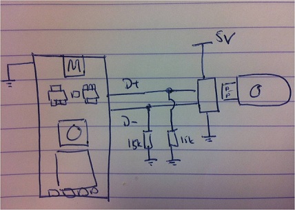
4. **Pull-Up Resistors**: The I2C bus requires pull-up resistors on the SDA (data line) and SCL (clock line) to ensure proper signal levels. Typical values for these resistors range from 4.7kΩ to 10kΩ, depending on the bus speed and capacitance.
5. **Power Supply**: Depending on the I2C client chips used, an appropriate power supply must be provided. This could be from the USB connection or an external power source, ensuring that voltage levels are compatible with the connected devices.
6. **Decoupling Capacitors**: These capacitors are placed close to the power pins of the I2C client chips to filter out noise and stabilize the power supply.
The overall design should ensure that all components are correctly connected and that the power requirements for each chip are met. Proper attention to the layout and routing of the I2C lines will help minimize interference and ensure reliable communication between the PC and the connected devices.
This setup not only simplifies the process of connecting I2C devices to a computer but also opens up a wide range of applications, including data logging, environmental monitoring, and automation, making it a valuable tool for developers and engineers in various fields.Attach any I2C client chip (thermo sensors, AD converter, displays, relais driver, to your PC via USB quick, easy and cheap! Drivers for Linux, Windows. 🔗 External reference
Related Circuits
Telephone ringer utilizing 556 dual timers. This circuit generates ringing tones resembling those of a telephone by employing modulated rectangular waves of varying time periods. The telephone ringer circuit employs two 556 dual timer ICs configured to generate modulated rectangular...
This is a Class D audio amplifier circuit that is used to control PWM motor speed. This circuit has two advantages for battery-powered portable devices. First, The Class D audio amplifier circuit is designed to efficiently manage the speed...
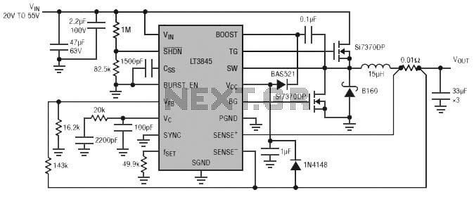
Burst Mode operation maintains high efficiency at light loads by reducing IC quiescent current to 120 µA. Light load efficiency is also improved with the reverse inductor current inhibit function, which supports discontinuous operation. Additional features include an adjustable...
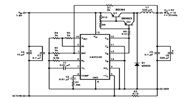
The schematic diagram below illustrates a 5V/1A Step-Down Switching Regulator utilizing the LM2524D Regulating Pulse Width Modulator (PWM). Additional parameters, PC board layout, stuffing diagram, and more information can be found in the LM2524D datasheet. The circuit design features the...
The software aspect is straightforward due to the Vodafone USB Modem library designed for mbed. This library is compatible with any of the cellular data plans provided by Vodafone. The primary limitation is geographical, as it is only available...

A simple frequency meter or frequency counter circuit featuring an LCD display and an AVR microcontroller. This includes a DIY schematic circuit diagram and embedded C code. The frequency meter circuit is designed to measure the frequency of input signals...