
Thermostat for 1KW Space Heater (SCR controlled) circuit
")
The described circuit utilizes a heating element that operates in conjunction with two SCRs arranged in a back-to-back configuration, allowing for controlled power delivery based on the alternating current (AC) supply. The SCRs serve as electronic switches that can handle high power loads, making them suitable for applications such as heating systems where precise control of the power is necessary.
The pulse transformer plays a critical role in the operation of this circuit. Its three identical windings are strategically utilized to ensure that the SCRs are triggered correctly. The first two windings are responsible for generating the trigger pulses that initiate the conduction of the SCRs. The third winding is connected to a PNP transistor pair, which functions to provide the necessary timing for the trigger pulses. This arrangement ensures that the SCRs are activated at the onset of each half-cycle of the AC waveform, allowing for efficient power control and minimizing the risk of overheating.
The alternating nature of AC voltage means that the polarity changes direction, which is why only one of the SCRs conducts at any given time. This is a critical feature of the design, as it prevents both SCRs from conducting simultaneously, which could lead to short-circuiting or damage to the components. By controlling which SCR is triggered based on the AC polarity, the circuit effectively manages the flow of current to the heating element, allowing for consistent and reliable operation.
In summary, this circuit design exemplifies an effective method for controlling a heating element using SCRs and a pulse transformer, ensuring efficient power management while maintaining safety and reliability in operation.The heater element (not shown) is connected in series with two back to back 16 amp SCRs (not shown) which are controlled with a small pulse transformer. The pulse transformer has 3 identical windings, two of which are used to supply trigger pulses to the SCRs, and the third winding is connected to a PNP transistor pair that alternately supply pulses to the transformer at the beginning of each AC half cycle.
The trigger pulses are applied to both SCRs near the beginning of each AC half cycle but only one conducts depending on the AC polarity.. 🔗 External reference
Related Circuits
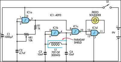
The circuit incorporates two oscillators, both operating at about 40kHz. The first, IC1a, is a standard CMOS oscillator with its frequency adjustable via VR1. The frequency of the second, IC1b, is highly dependent on the inductance of coil L1,...

The circuit outputs 12V at 10A and utilizes a high-current switching power supply design based on the L296 component. This configuration allows for an output current of up to 10A, and the entire circuit is compact with minimal component...
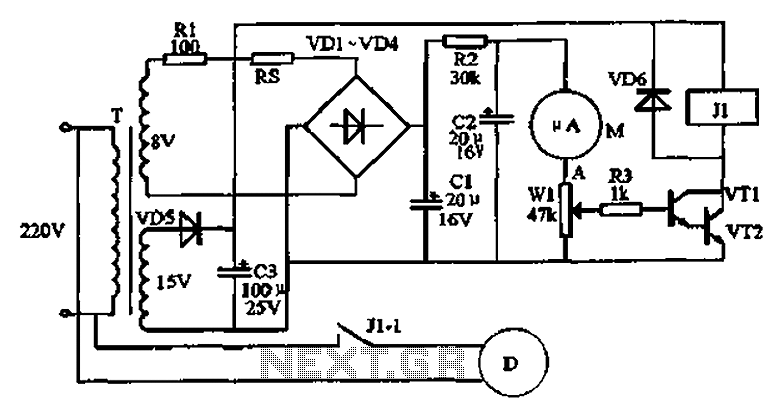
An automatic humidifier can be utilized for humidity control in households, hatcheries, poultry farms, or juvenile poultry houses. When the humidity level falls below 50%, the automatic humidifier activates to maintain a specific humidity level that is beneficial for...
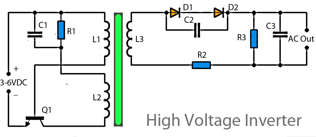
This inverter circuit operates using a transistor and transformer, along with other components, to elevate the voltage. The input supply voltage ranges from 3V to 6V DC, which is then converted to a high voltage AC output. However, the...
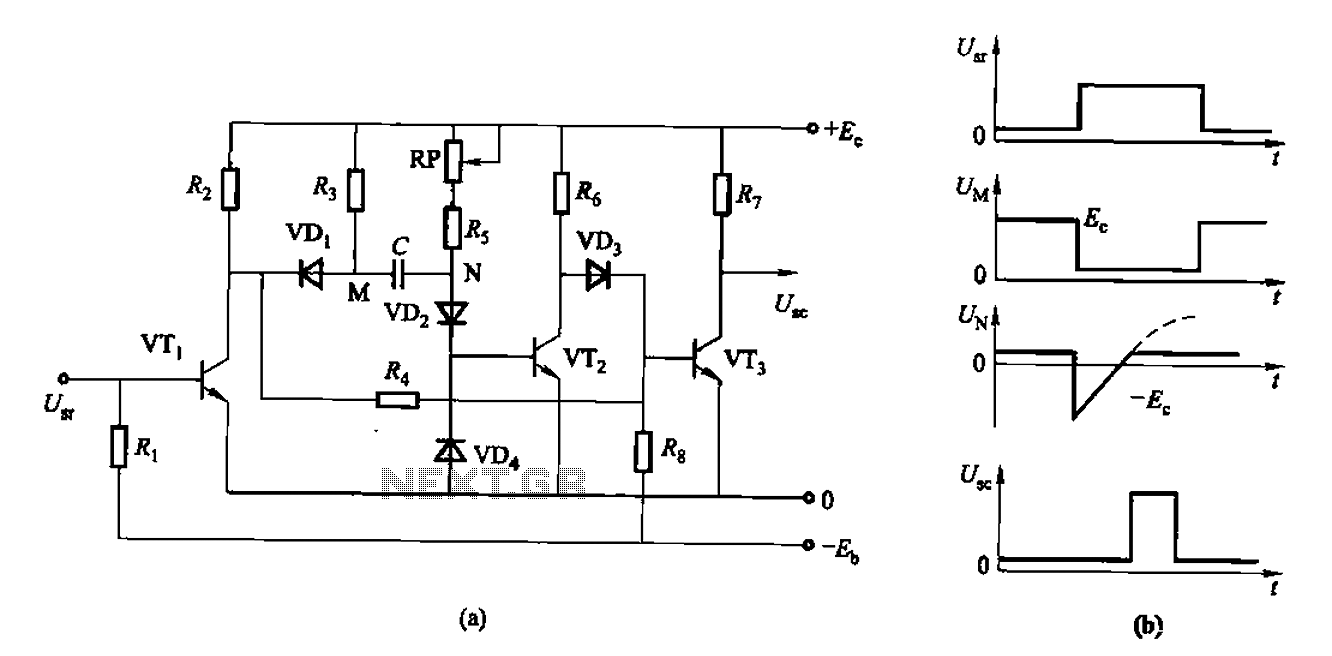
The circuit described is a discharge delay circuit that offers a longer delay compared to a standard rechargeable delay circuit, while also maintaining relatively high accuracy. The schematic diagram illustrates the input and output waveforms. Typically, when there is...
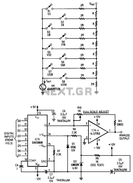
Figure A illustrates an R/2R resistor ladder. Each closed switch increases the current flow. A basic channel A/D converter is depicted in Figure B. The voltage reference (D2) is shared across all channels, although the value of the dropping...