
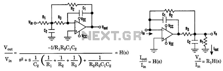
Three amplifier active filter

The state variable filter is a versatile circuit design that provides multiple output types, including bandpass, high-pass, and low-pass signals. This configuration is particularly useful in applications where different frequency components of a signal need to be isolated or processed separately. The core of this filter consists of three operational amplifiers (op-amps) and two capacitors, which work together to create a stable and tunable filtering system.
In this filter design, the first op-amp is configured as a high-pass filter. It allows high-frequency signals to pass while attenuating lower frequencies. The output of this stage is then fed into the second op-amp, which is configured as a low-pass filter. This stage allows low-frequency signals to pass while attenuating higher frequencies. The third op-amp combines the outputs of the first two to create a bandpass output, which selectively allows a specific range of frequencies to pass through while rejecting frequencies outside this range.
The use of only two capacitors in this design simplifies the circuit and reduces component count, making it cost-effective and easier to implement. The frequency response of each output can be adjusted by varying the values of the capacitors and resistors in the circuit, allowing for a high degree of flexibility in tuning the filter for specific applications.
This active filter design is widely utilized in audio processing, signal conditioning, and communication systems, where precise frequency selection is crucial for optimal performance. The state variable filter's ability to produce multiple outputs from a single configuration makes it a preferred choice in many electronic applications.The active filter is a state variable filter with bandpass, high-pass and low-pass outputs It is a classical analog computer method of implementing a filter using three amplifiers and only two capacitors.
Related Circuits

The circuit diagram illustrates an operational amplifier (op-amp) based subwoofer filter. Audio frequencies below 200 Hz are classified as subwoofer frequencies, thus the subwoofer filter functions as a low-pass filter with a cutoff frequency of 200 Hz. The operation...
The recommendation regarding the existing phono connector is to maintain its current configuration without making significant alterations. The procedure involves replacing the electrolytic and paper capacitors, adding a three-wire line cord, and utilizing the radio in its original state....
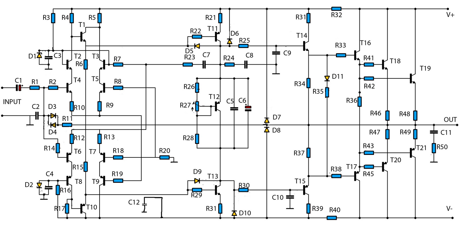
This is a mono amplifier circuit with a high output power of 1400W. It is well-suited for use in large rooms with woofer and full-range speakers, delivering a loud and clear sound with minimal noise. The amplifier utilizes high-quality...
This cable TV amplifier circuit is an RF amplifier designed for quick installation between two coaxial cables. Both the input and output impedances are compatible with 75-ohm cables. The main amplifier is the T1 transistor, while T2 functions as...
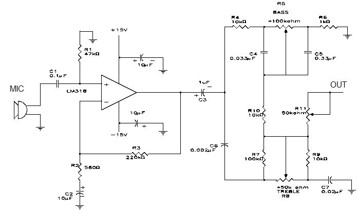
This electronic project is a simple microphone preamplifier based on the LM318 operational amplifier. The LM318 is configured as a standard non-inverting amplifier. Resistor R1 provides a ground reference for the bias current of the non-inverting input. The combination...
The low-pass Sallen-Key filter is a staple for designers because it contains few components. By redesigning the filter, a current-to-voltage conversion can be avoided when the input signal to be filtered is in current form. The Sallen-Key filter is a...