
three channel audio splitter

The circuit operates by first receiving the audio signal at connector J1, which serves as the input interface. The signal then travels through potentiometer P1, allowing for adjustable gain control. This component is crucial for fine-tuning the amplitude of the audio signal before it reaches the amplifier stage.
Following the potentiometer, the signal is directed to integrated circuit IC1, which functions as the main amplification unit. This IC is selected for its ability to provide high fidelity amplification while maintaining low distortion levels. The output from IC1 is split into three separate paths, enabling the circuit to drive multiple audio lines simultaneously. Each output is designed to maintain a consistent impedance of 300 ohms, ensuring compatibility with standard audio equipment and minimizing signal loss.
The circuit may also include bypass capacitors and filtering components to eliminate noise and enhance the overall audio quality. The layout should be carefully designed to minimize interference and ensure stable operation across various audio frequencies. Proper grounding and shielding practices should be implemented to further improve performance and reliability in real-world applications.This circuit is suitable to amplify and distribute the audio signals. The input audio signal is applied to the J1 and after passing through the P1, It is buffered and amplified by the IC1 prepared to redistribute. It has 3 outputs to drive 3 audio lines with 300 ohms impedance.. 🔗 External reference
Related Circuits
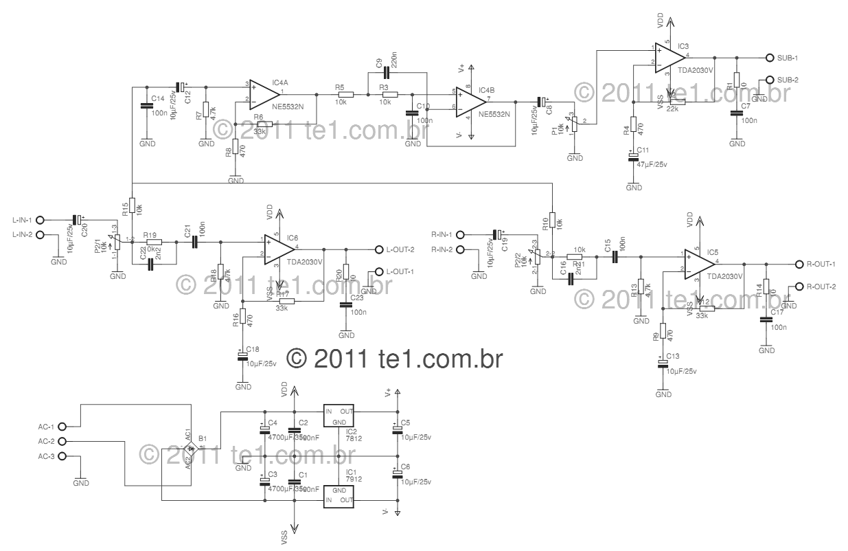
This circuit is a complete application for a 2.1 amplifier system, consisting of two satellite speakers powered by a TDA2030 and one subwoofer. This 2.1 system is commonly utilized in commercial applications as an amplifier for computers, enhancing audio...
Class D amplifiers are significantly more efficient than traditional amplifiers; however, this high efficiency is accompanied by increased noise and distortion. The frequency and time-domain characteristics of a Class D amplifier, including its output filter, can be evaluated using...
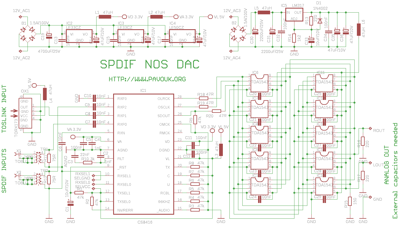
This circuit is an experiment designed to build a high-quality digital-to-analog converter (DAC) with optical input (TOSLINK), electrical input (S/PDIF), and USB input. Both electrical inputs are galvanically isolated from the DAC. The circuit is intended as part of...
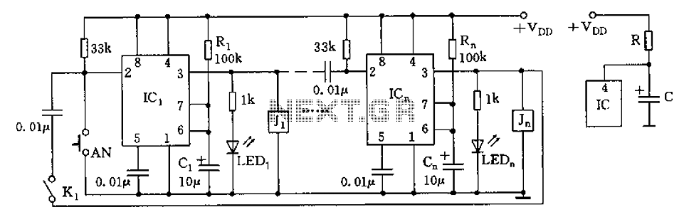
The circuit depicted in the figure is designed for multi-temperature testing, allowing for the switching of the thermocouple corresponding to the active channel. At the core of this design is a 555 timer configured in a monostable delay mode....
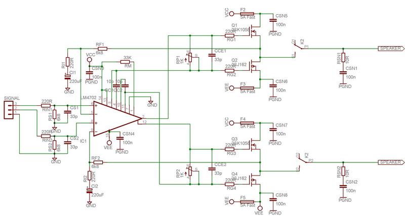
The LM4702 has been integrated into a Crown DC150 amplifier. The driver board in the Crown was damaged, but the power supply remains functional. The LM4702 is a high-performance audio amplifier IC designed for use in various audio applications, including...
The LM2876 audio power amplifier circuit can be designed as a simple, high-efficiency audio amplifier capable of delivering 40W of continuous average power to an 8-ohm load with a total harmonic distortion plus noise (THD+N) of 0.1% from 20Hz...