
555-channel temperature test circuits

The circuit operates effectively by utilizing two 555 timer ICs configured in a monostable mode to manage the timing and switching of the thermocouple channels. The first timer (IC1) initiates the measurement process, while the second timer (IC2) ensures the thermocouple is activated for the duration of the measurement. The use of a capacitor (C1) and resistor (R1) not only defines the timing characteristics but also stabilizes the output by preventing sudden voltage changes that could lead to inaccurate readings. The configuration ensures that when the circuit is powered, the initial flickering of the LEDs indicates the system is operational, while the R-C network enhances the reliability of the reset mechanism, providing a more consistent and accurate measurement cycle. The design is particularly useful in applications requiring precise temperature monitoring across multiple channels, making it suitable for laboratory testing and industrial applications where temperature variations are critical. Circuit shown in Figure, when used in multi-temperature test, switch the thermocouple corresponding channel. 555 brightest are at the core monostable delay circuit, such as Cli ck AN, because the 2-pin was low, the IC1 set, was 3 feet high, J1 pull, the thermocouple channel ON. Meanwhile, C1 through R1 charging it, when the charging voltage reaches the threshold level 6 feet 2/3Vdd, the 555 reset pin 3 referred to the low level, in turn triggering a second stage IC2, the IC2 set, turns ON Road thermocouple, and then click the trigger.
If J1 is closed, the cycle can be monitored. Each level of the delay time (ie measuring time) td 1.1R1C1, icon parameter corresponding delay is about 1 second. LED1 ~ LEDn LEDs also turn lights, as a monitoring indicator. Figure a circuit when power-up, there are a few pieces of LED light tubes flicker at the same time, therefore, to improve the circuit shown in Figure b.
After accessing R, C network, boot, since C voltage can not change suddenly, so that the reset terminal pin 4 is forced reset state, 3 feet showed low output, as the charging capacitor C, so that was 4 feet high level, IC trigger timing in a wait state levels, have improved the accuracy of the test.
Related Circuits
The ICs LM4651 and LM4652 are types of MOSFET integrated circuits and power amplifiers that include high-efficiency amplifiers, making them suitable for self-powered speakers, subwoofers, and high-quality car audio systems. The LM4651 is a fully integrated conventional pulse width...
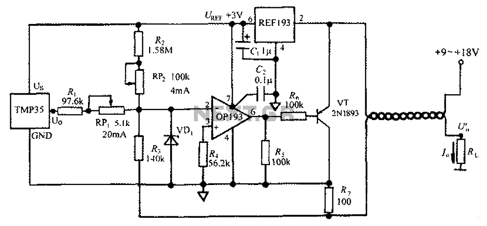
The circuit consists of a TMP35 temperature transmitter that converts a voltage signal output from the TMP35 into a standard 4 to 20 mA current signal. This configuration is suitable for use in automated instrumentation and industrial temperature control...
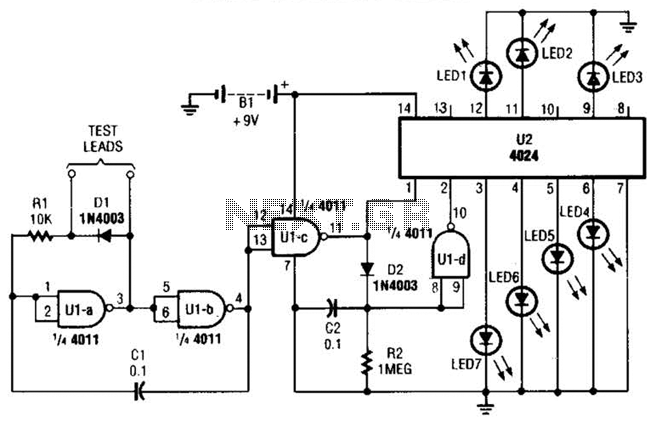
By observing the frequency at which a specific LED flashes, it is possible to estimate the resistance value. The circuit comprises two integrated circuits (ICs): a 4011 CMOS quad 2-input NAND gate (U1) and a 4024 binary counter (U2),...
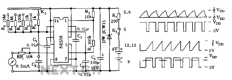
The tester comprises a dual time base circuit using a 556 timer and various RC components. The right side of the circuit features the 556 timer (556 1/2) along with resistors R2, R3, capacitors C2, C3, and additional components...
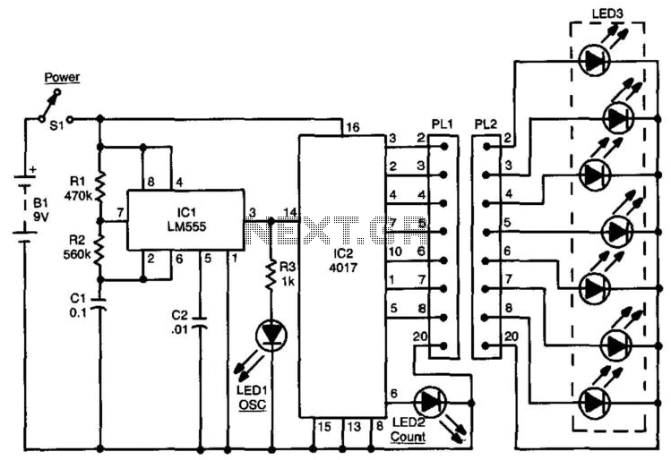
This circuit can be used to check up to an eight-conductor cable. IC1, a 555 timer, drives decade counter IC2, a 4017. Each LED should light in sequence. The cable to be tested is connected between PL1 and PL2....
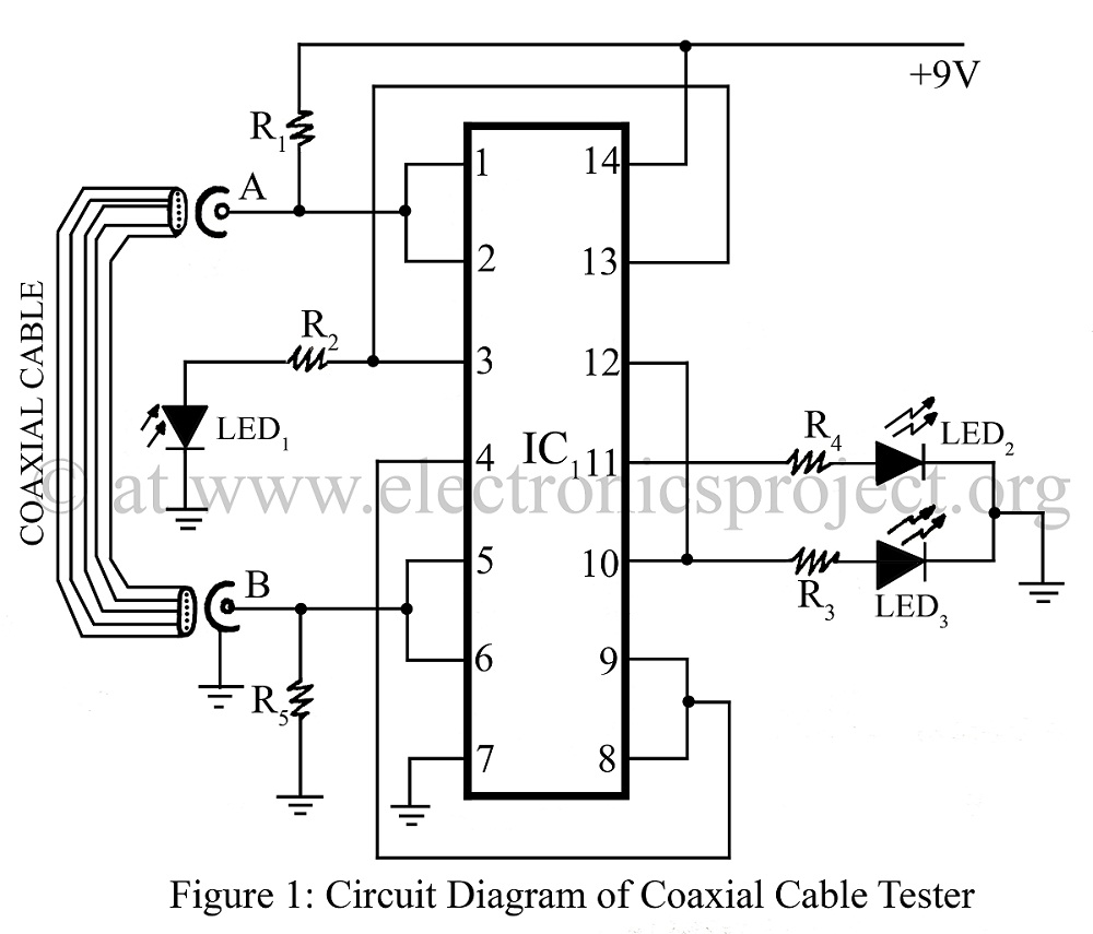
A coaxial cable tester is utilized to determine the condition of a coaxial cable, identifying whether it is open, short-circuited, or functioning correctly. This device employs a digital IC 4001 and includes a circuit description along with a parts...