
Power Amplifiers Audio Circuits

Class D amplifiers utilize pulse-width modulation (PWM) to achieve high efficiency, where the output transistors operate in saturation or cut-off states, minimizing heat generation. This design allows for compact implementations suitable for portable devices and high-power applications. The digital amplifier discussed operates on a 13.5-Volt supply and can produce 20W per channel, making it suitable for a range of audio applications, including home theater systems and portable speakers.
The Linkwitz transform circuit enhances the performance of subwoofers by allowing adjustments to the frequency response, enabling a flat output across a wide range of frequencies. This flexibility is particularly beneficial in sealed enclosures, where the acoustic characteristics can be fine-tuned for optimal sound reproduction. The parameters of the transform circuit, such as the cutoff frequency and gain, can be adjusted to suit various speaker designs and enclosure sizes.
The active crossover network plays a crucial role in audio systems by dividing the audio signal into different frequency bands, directing low frequencies to the subwoofer while sending mid and high frequencies to other speakers. This separation ensures that each speaker operates within its optimal frequency range, enhancing overall sound quality and preventing distortion.
For designers, the availability of a spreadsheet calculator facilitates the selection of appropriate component values, allowing for customization of the circuit to meet specific design requirements. This tool can assist in optimizing the performance of the amplifier and equalization circuit, ensuring that the final audio output meets the desired specifications.Class D amplifiers are much more efficient than other Classical amplifiers, but their high efficiency comes at the expense of increased noise and distortion. You can assess the frequency- and Time-domain characteristics of a Class D amplifier, including the output filter, using online simulations.
Class T Digital Audio Amplifier Evaluation Board This application note describes a digital amplifier, which operates from13. 5-Volt power source and outputs up to20W poor channel power. The application note is in PDF format. Uses a Digital Power Processing Technology EB TA2020 from Tripath Technology. Subwoofer Equalizer : The Linkwitz transform circuit is a hugely flexible way to equalize the bottom end of a sealed loudspeaker enclosure. A speaker that is corrected using this method is flat from below resonance to the upper limit of the selected driver.
The low frequency roll off point is determined by the parameters of the transform circuit. Should the enclosure size be too small and cause a lump in the response before roll off, this is also corrected. A conventional active crossover network is then used to divide the subwoofer signal from the main channel signals.
Note that there is also a separate spreadsheet calculator available for calculating component values for different situations not handled by the original circuit. 🔗 External reference
Related Circuits
An increasing number of appliances draw a very small current from the power supply. If designing a mains-powered device, it is generally advisable to consider the current requirements. The trend of modern appliances utilizing minimal power consumption necessitates careful consideration...
The purpose of this timer is to disconnect the compressor circuit and connect a resistive heating element located near the evaporator at regular time intervals. The defrost heater is controlled by a thermostat and is used to melt any...
The soft start circuit refers to a power circuit where the output voltage gradually increases to a specified value, thereby protecting the load circuit from unwanted voltage surges. It can output a voltage of 24V and a current of...
The Kill A Watt is a product that measures volts, amps, and power factor of individual appliances, allowing users to calculate power consumption and running costs. However, a desire for a solution that provides similar data for an entire...
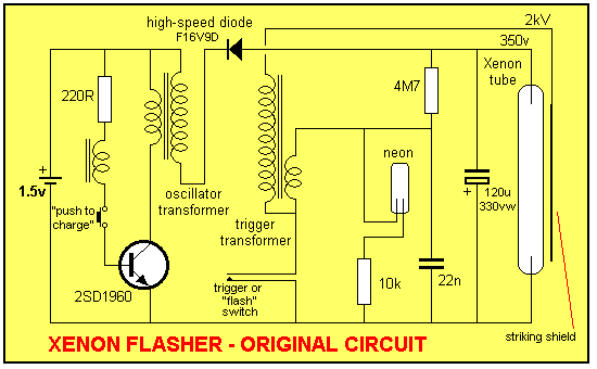
This discussion covers three different Xenon flashing circuits from disposable cameras. From these circuits, unique techniques not found in any theoretical literature will be presented. The first circuit consists of six building blocks. An old disposable flash camera and...
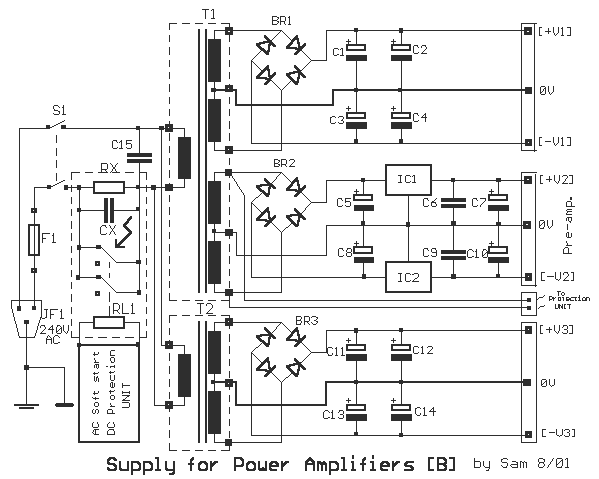
Proposed power supply for amplifier 100W v-mosfet is what appears in the above form. It has separated supply for the various stages of supply, stage for power, stage for control, supply for preamplifier and for stage of protection. Whoever...