
Three Hour Timer

This circuit serves as an effective battery management system for cordless drill chargers, ensuring safe operation and preventing overcharging. The relay Re1 acts as a crucial component in controlling the charging current, providing a physical disconnection once the battery has been charged for the predetermined duration. The use of ten LEDs for visual feedback is particularly advantageous, as it allows users to monitor charging progress in real-time, enhancing user experience and safety.
The timing mechanism relies on an integrated circuit (IC3) and associated passive components, including resistors (R5) and capacitors (C4 and C3), to create a reliable timing function. The adjustable potentiometer P1 enables customization of the charging duration, accommodating different battery specifications and user preferences. The design acknowledges the inherent limitations of timing accuracy but ensures that the error margin is tolerable for practical applications.
Upon initial power-up, the circuit experiences a unique behavior where the first timing cycle is extended. This phenomenon is due to the charging characteristics of capacitor C3, which must reach a specific voltage level before the timing sequence stabilizes. This characteristic should be considered during the design and testing phases to ensure that the circuit performs optimally under various conditions.
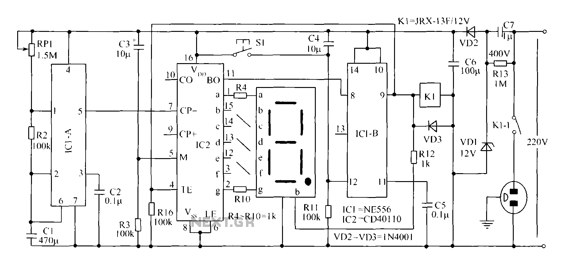
Overall, this circuit design exemplifies a practical solution for managing battery charging in cordless drills, integrating user-friendly features with essential safety mechanisms.Manufacturers of cordless drills generally recommend a battery charging time of three hours. Once the charging time is up the battery must be disconnected from the charger: if you forget to do this there is a danger of overcharging the battery. This circuit, which sits between the charger circuit and its battery socket, prevents that possibility:
the contact of relay Re1 interrupts the charging current when the three hours are up. Ten LEDs show the remaining charging time in steps of 20 minutes. The timer is reset each time power is applied and it is then ready for a new cycle. When power is applied IC3 is reset via C4 and R5. When the charging time has elapsed, Q9 (pin 11) goes high, which turns the relay on and interrupts the charging current. Since Q9 is connected to the active-low EN (enable) input, the counter will now remain in this state.
The charging time can be adjusted from about 2 hours 15 minutes to 4 hours 30 minutes using P1. The author set P1 to 30 k, giving a charging time of 3 hours 7minutes. The greater the resistance of P1, the shorter the charging time. The timing of the circuit is not particularly precise, but its accuracy is entirely adequate for the job. When adjusting the charging time it is worth noting that therst clock cycle after the circuit is turned on (from Q0 to Q1) is longer than the subsequent ones.
This is because initially capacitor C3 has to be charged to around half the supply voltage. 🔗 External reference
Related Circuits
This is a programmable clock timer circuit that utilizes individual LEDs to signify hours and minutes. Twelve LEDs can be arranged in a circular formation to represent the 12 hours of a clock face, while an additional 12 LEDs...

This circuit is a compact timer designed to keep the headlights of a car illuminated for approximately 1.5 minutes before automatically turning them off. By integrating this circuit into a vehicle, users can access dark areas without the need...
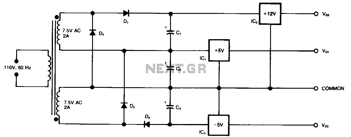
This circuit generates three supply voltages using a minimal number of components. Diodes D2 and D3 perform full-wave rectification, alternately charging capacitor C2 during both halves of the AC cycle. Meanwhile, diode D1 in conjunction with capacitor C1, and...
This circuit was developed in response to requests from visitors of this website for a timer that can emit a beep after one, two, three minutes, and so on, for jogging purposes. As illustrated in the circuit diagram, SW1...
A novel timing switch circuit features a "Variable Timing" adjustment function in addition to a standard timing circuit. It also includes a countdown display feature, which indicates the remaining time of the timing circuit, making it particularly useful. The...
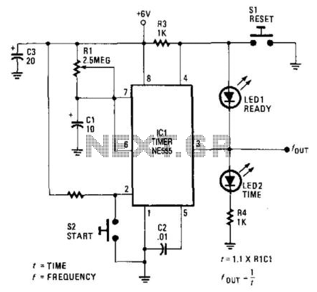
LEDs provide a visual indication of the circuit's status at any moment. Once the reset switch, SI, is activated, the timer maintains that state until the start switch, S2, is pressed. When either switch is engaged, LED1 (indicating "ready")...