
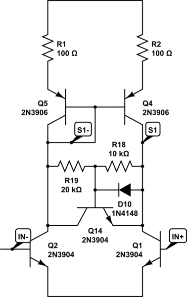
THREE INPUT TWO OUTPUT MIXER

The circuit employs two common-cathode video mixers, which are integral components for combining multiple video signals while maintaining the integrity of the individual signals. Each mixer operates independently, allowing for flexibility in signal processing. The design incorporates identical heading markers at the front input 2 of both mixers, ensuring that both channels are synchronized for a cohesive output.
The remaining inputs of the mixers are dedicated to handling independent markers, which allows for the integration of various signal sources without interfering with the primary synchronization provided by the common markers. This configuration is particularly useful in applications where multiple video feeds need to be processed simultaneously, such as in broadcasting or complex video editing environments.
The use of common-cathode mixers is advantageous due to their ability to provide high linearity and low distortion when combining signals. These mixers typically consist of transistors or operational amplifiers configured to operate in a common-cathode arrangement, which enhances performance by improving signal fidelity.
The reference to the "Hand-book Preferred Circuits Navy Aeronautical Electronic Equipment" indicates that this design is grounded in established practices, ensuring reliability and effectiveness in high-stakes environments such as aeronautics. The publication from 1963 serves as a historical context, showcasing the long-standing relevance of these circuit designs in electronic engineering. Overall, this circuit design exemplifies a robust approach to video signal processing, suitable for a variety of applications where precision and reliability are paramount.Uses two separate common-cathode video mixers. Same heading markers are inserted into both mixers front input 2, while other inputs handle independent markers. -NBS.
"Hand-book Preferred Circuits Navy Aeronautical Electronic Equipment, " Vol. 1, Electron Tube Circuits, 1963, p N4-3.
🔗 External referenceRelated Circuits
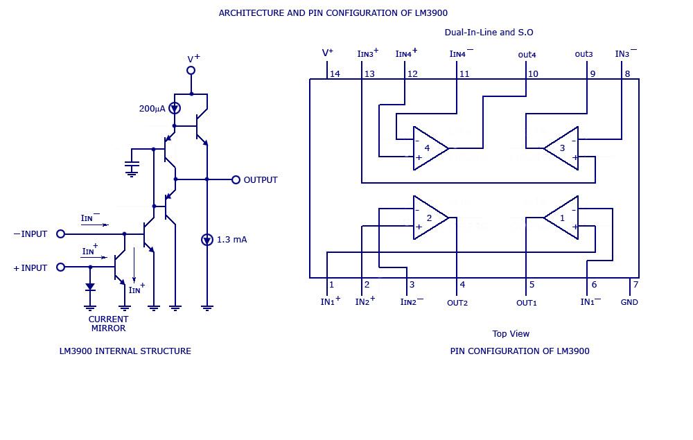
By adding the same circuit in parallel, the number of inputs can be increased according to the applications. Each input is connected to the inverting terminal of the LM3900. The built-in amplifier of each section amplifies every audio input...
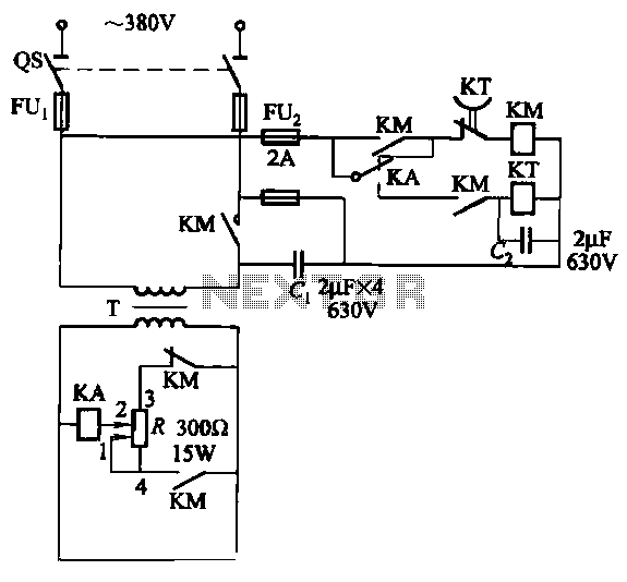
The relays in the AC arc welding machine manage the load through a three-way power circuit, as depicted in Figure 522. The selected relay type is KA, operating at 24V. Additionally, the time relay KT is of the JS7...
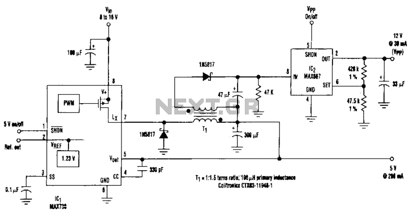
By adding a flyback winding to a buck-regulator switching converter, which functions as a 5-V supply with a 200-mA output capability, a 12-V output can be generated. The flyback winding on the main inductor, forming transformer T1, allows for...
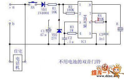
Utilize the 48V (60V) DC feedback electric current supplied by the phone feedback line as the operational energy source for the electronic doorbell, which is highly economical and practical. This document introduces a two-tone doorbell circuit that operates without...
The amplifier in the following schematic, when simulated, demonstrates the ability to effectively amplify a signal with an amplitude of 0.1V to 10V. However, when subjected to a larger input signal, the performance deteriorates significantly during the positive half...

The circuit connection is illustrated in figures a and b. In figure a, a star-shaped winding is used with shunt capacitance, while figure b depicts a triangular winding with capacitance connected in parallel. The working capacitance (Cc) is calculated...