
Add 12V Output To 5V Buck Regulator Circuit

The circuit described integrates a buck-regulator switching converter configured to provide a stable 5-V output with a current capacity of 200 mA. The addition of a flyback winding on the inductor (designated as T1) transforms the basic buck converter into a more versatile power supply capable of generating a higher voltage output of 12 V. This is achieved by utilizing the energy stored in the inductor during the buck conversion process, which is then transferred via the flyback winding.
The flyback winding operates by inducing a voltage when the magnetic field collapses, effectively allowing the converter to step up the voltage. This induced voltage is subsequently regulated down to the required 12 V using a low-dropout linear regulator (IC2). This type of regulator is particularly advantageous in applications where the input voltage is only slightly higher than the desired output voltage, as it minimizes power loss and heat generation.
The input voltage for this circuit is specified to be within the range of 8 to 16 V, ensuring that the buck converter operates efficiently while providing adequate headroom for the linear regulator. This design is particularly suitable for applications requiring precise voltage levels, such as programming EEPROMs, where stable and reliable power supply is critical. The combination of the buck converter and flyback winding allows for a compact and efficient solution to meet the voltage requirements of modern electronic components. By adding a flyback winding to a buck-regulator switching converter (see the figure), wliich is essentially a 5-V supply with a 200-mA output capability, a 12-V output ) can be produced. The flyback winding on the main inductor (forming transformer Tl) enables an additional low- dropout linear regulator (IC2) to create the 12-V output voltage that`s needed to program EEPROMs.
The required input voltage is 8 to 16 V.
Related Circuits
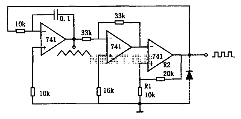
The circuit illustrated generates a variety of low-frequency waveforms, specifically triangle and square waves, simultaneously. It consists of several stages: the first stage is an integrator, followed by a gain stage with an inverter, and a comparator stage that...
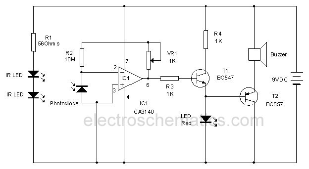
This infrared alarm barrier is designed to detect individuals passing through doorways, corridors, and small gates. The transmitter emits an infrared light beam that is not visible to the human eye. When the beam is interrupted by a person,...
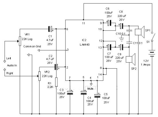
The LA4440 audio amplifier IC can be utilized to design a straightforward stereo power audio amplifier project, capable of delivering 6 watts of output power into an 8-ohm load. This audio amplifier IC features a minimal number of external...
The example below illustrates the use of an operational amplifier (op-amp) as an audio amplifier in a basic intercom system. A small 8-ohm speaker is utilized as a microphone, which is connected to the op-amp input through a 0.1...

The circuit integrates several functions, including a smooth startup for the AC power line, with a one-second delay before connecting to the power supply transformers of the amplifier through relay RL1 and resistor Rx. This delay is designed to...

The device is referred to as the Itsy Bitsy USB Lamp. This concept is remarkably straightforward, raising the question of why it had not been conceived earlier. Originating as a student project at Massey University in Wellington, New Zealand,...