
multi channel audio mixer using lm 3900

The described audio mixer circuit employs the LM3900 operational amplifier, which is configured to handle multiple audio inputs. Each input signal connects to the inverting input of the LM3900, allowing for the summation of audio signals while maintaining low distortion. The architecture supports parallel connections, enabling scalability in the number of inputs based on application requirements.
The circuit's design ensures that each audio channel is amplified individually, thanks to the built-in amplifiers of the LM3900. This configuration is particularly beneficial in applications where multiple audio sources need to be mixed without interference. The output from each channel is routed to a single output line, which is designed to have a maximum resistance of 680K ohms. This resistance level is critical in minimizing signal degradation and noise, resulting in a clean mixed audio output.
Decoupling capacitors C1 to C4 are integral to maintaining signal integrity by filtering out unwanted noise and stabilizing the power supply for each channel. C5, the output decoupling capacitor, serves a similar purpose at the output stage, ensuring that the final mixed signal is free from power supply fluctuations.
In scenarios where the power supply circuit is situated at a distance from the mixer circuit, the inclusion of a 100µF/50V electrolytic capacitor between the positive supply rail and ground is essential. This capacitor helps to smooth out voltage variations, thereby enhancing the overall performance and reliability of the audio mixer circuit.
Overall, this audio mixer design is suitable for various applications, including live sound reinforcement, recording studios, and multimedia installations, where multiple audio sources need to be combined efficiently while maintaining high audio quality.By adding the same circuit parallel with this, you can increase the number of inputs according to the applications. Each input is connected to the inverting terminal of LM3900. The built in amplifier of each section amplifies every audio input separately and is fed to the output terminals.
The output terminal from each channel is connected to a si ngle output line with a resistance not greater than 680K and produces a mixed audio at the output with very low noise. This audio mixer circuit doesn`t use a low impedance input to mix idealsources. Capacitors C1 to C4 are the decoupling capacitors for the corresponding channels. C5 is the output decoupling capacitor. If the power supply circuit is far from the mixer circuit, then a 100uF/50V electrolytic capacitor must be connected from the positive supply rail to the ground.
🔗 External reference
Related Circuits
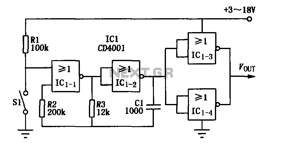
The core elements of this circuit are the second four-input NOR gate terminal IC CD4001. The entire circuit features a simple structure, with fewer components, making it easy to construct, particularly for remote control transmitters or carrier modulation transmission....
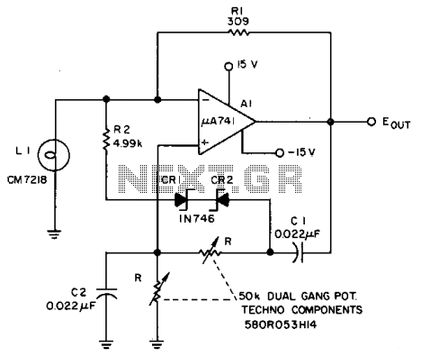
The Lamp LI stabilizes the loop gain at higher frequencies, while the limiting action of R2, CRI, and CR2 prevents clipping at low frequencies and increases the frequency adjustment range from approximately 3:1 to over 10:1. Additionally, waveform purity...

This circuit is designed as a pocket-sized, high-performance audio oscillator. It can operate using a battery-powered version, which is feasible at a very low cost by utilizing a single quad op-amp to provide the entire active circuitry. The design...
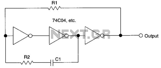
This circuit employs a protective resistor R2 along with a feedback resistor R1. Together, these components create a voltage divider that lowers the input voltage amplitude for IC1-a, ensuring that the protective diodes remain inactive. This arrangement enhances the...
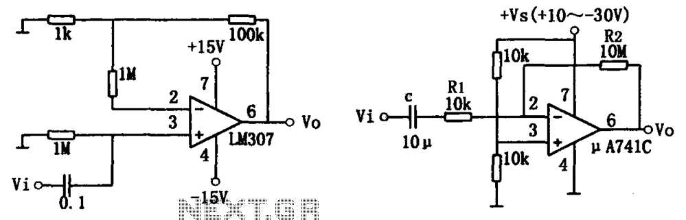
The simple audio amplifier circuit is illustrated in the figure. Utilizing an integrated op-amp configuration, this audio amplifier is stable and allows for easy negative feedback, facilitating the achievement of equalization characteristics. Additionally, the crosstalk between channels is minimal,...
This is a simple circuit that features high-performance power amplifiers. The power amplifier is available as a PCB, along with a complete list of components. The described circuit utilizes high-performance power amplifiers, which are essential for applications requiring significant signal...