
THREE INPUT TWO PENTODE MIXER

In this circuit design, the integration of distance markers and intermediate frequency (IF) signals is accomplished by utilizing a dual-grid tube configuration. The first tube is configured to accept both distance markers and IF signals at distinct grids, ensuring that these two types of signals do not interfere with each other. This separation is crucial for maintaining signal integrity and clarity during processing.
The second tube in the circuit is a pentode, which is particularly effective in amplifying weak signals due to its additional control grid. In this configuration, the radar video signal sourced from input 3 is applied to the control grid of the pentode. This allows for effective modulation and amplification of the radar video, which is essential for radar signal processing applications.
The use of a pentode in this context is significant, as it provides enhanced performance characteristics such as high gain and low noise, which are critical in radar systems. The design ensures that the radar video signal can be processed efficiently without degradation, enabling accurate distance measurement and signal interpretation.
Overall, this circuit exemplifies a sophisticated approach to radar signal processing, leveraging the unique properties of electron tubes to achieve reliable performance in aeronautical electronic equipment. The careful arrangement of signals and the choice of components reflect a deep understanding of electronic circuit design principles, particularly in the context of radar technology.Distance markers and iff signals are inserted at separate grids on one tube, while radar video from input 3 is impressed on control grid of other pentode. -NBS, "Handbook Preferred Circuits Navy Aeronautical Electronic Equipment, " Vol. l, Electron Tube Circuits, 1963, p N4-4. 🔗 External reference
Related Circuits
This circuit combines two or more audio channels into a single channel (for example, mixing stereo into mono). The design allows for the addition of multiple channels, consuming minimal power. Although the schematic illustrates two inputs, it is possible...
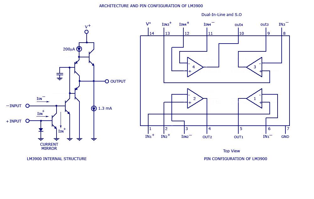
By adding the same circuit in parallel, the number of inputs can be increased according to the applications. Each input is connected to the inverting terminal of the LM3900. The built-in amplifier of each section amplifies every audio input...
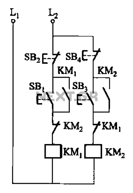
A, B, and two electric motors allow simultaneous operation through interlock control. The two motors can be connected in series with each other using normally closed contacts in the respective coil circuit. The circuit design facilitates the interlocking operation of...
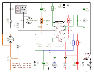
This is a two-zone alarm system featuring automatic exit, entry, and siren cut-off timers. It can be activated by standard normally-closed input devices, such as magnetic reed contacts, foil tape, and passive infrared sensors (PIRs). The circuit operates on...
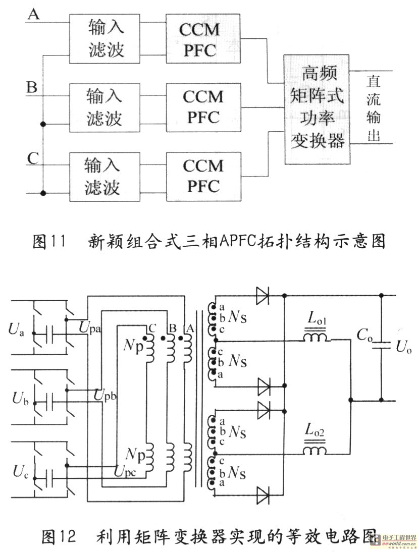
Tape isolate single-phase power factor correction (PFC) that utilizes DC/DC converters, consisting of two cables. The three-phase PFC is formed by connecting three single-phase PFCs in parallel at the output. This configuration is based on a matrix-type DC/DC converter...
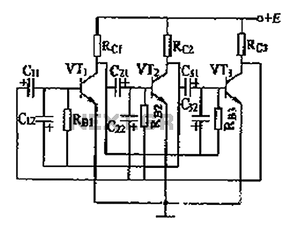
The three astable circuit is illustrated, demonstrating that each level of the transistor's base is connected by a capacitor between the two levels, ensuring tight coupling. Additionally, each base electrode is biased through a resistor (Rb) connected to the...