
Three-Level Audio Power Indicators

The audio output power indicator circuit is designed to visually represent the power level of an audio amplifier through the use of three light-emitting diodes (LEDs). Each LED corresponds to a specific range of output power, providing a clear and immediate visual cue of the amplifier's performance.
The circuit typically operates by monitoring the output voltage of the amplifier. A voltage divider may be employed to scale down the output voltage to a manageable level suitable for the LED driver circuit. The LEDs are then connected to a comparator or a series of comparators that are configured to turn on at predetermined voltage thresholds.
For instance, the first LED may illuminate at low power levels, indicating safe operation, while the second LED activates at a medium power level, suggesting that the amplifier is approaching its limits. The third LED lights up at high power levels, alerting the user to potential overdrive conditions.
To ensure accurate operation, resistors are used to limit the current flowing through each LED, preventing damage and ensuring longevity. Additionally, capacitors may be included in the circuit to filter any noise from the power signal, providing a more stable and reliable indication of output power.
This circuit can be integrated into various amplifier designs, enhancing usability by providing real-time feedback on audio output levels. It is an effective tool for audio enthusiasts and professionals alike, allowing for better management of amplifier performance and preventing potential damage due to overdriving.This circuit indicates audio output power via three LEDs. Nice addon to your amplifier.. 🔗 External reference
Related Circuits
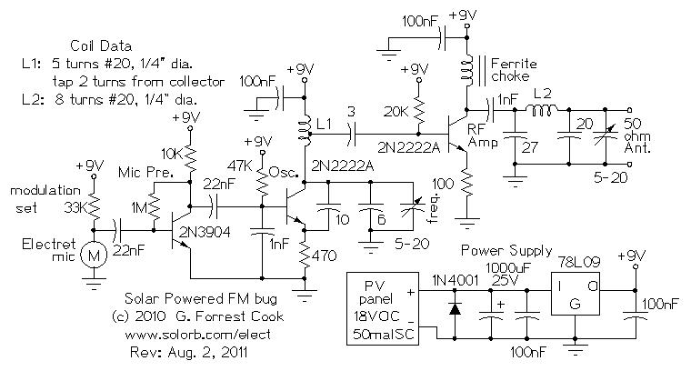
Numerous miniature FM transmitter bug circuits are available online; however, this particular design is distinctive as it operates entirely on solar power, eliminating the need for a battery. The transmitter will function as long as sunlight is incident on...
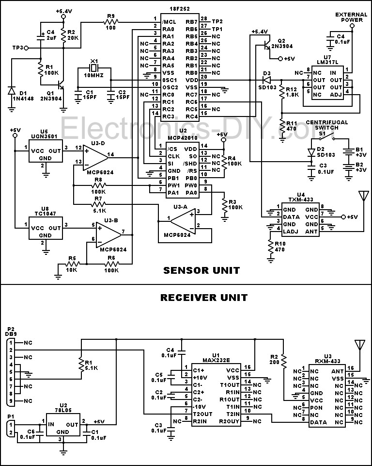
This device is designed to measure the torque in an automobile drive shaft and provide output to a vehicle data recording system or a portable computer via an RS-232 interface. The received data can then be combined with RPM...
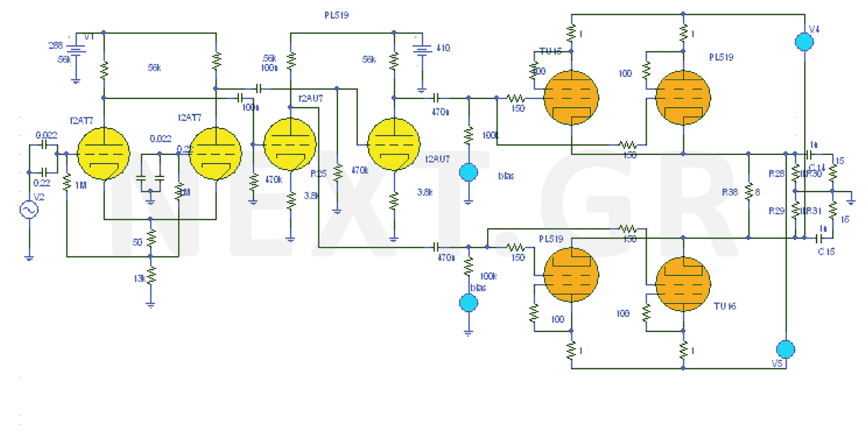
The design of the 40W Valve Amplifier is illustrated in the accompanying figure. Valve amplifiers are characterized by a prominent presence of second and third harmonics, sometimes accompanied by fourth and fifth harmonics, but always with a wider bandwidth....
This schematic is an improved version of the Pro Maniac Guitar tube power amplifier. The improved version of the Pro Maniac Guitar tube power amplifier features several enhancements aimed at increasing performance, reliability, and sound quality. The schematic typically includes...
This document outlines a basic circuit designed to power high impedance, high voltage, low current devices such as electroluminescent (EL) backlights and fluorescent tubes. The project originated from the need for a simple yet flexible inverter circuit for an...
All miniature electronic devices operate on batteries. Some require voltages higher than the standard battery voltages for efficient operation. When a battery of the specific voltage is unavailable, it becomes necessary to connect additional cells in series to increase...