
Horsepower Monitor

This torque measurement device operates by utilizing a sensor unit that is securely mounted to the automobile's drive shaft. The sensor detects the torque applied to the drive shaft during vehicle operation. The data collected by the sensor is transmitted wirelessly to a receiver unit using a 433 MHz RF data link, ensuring reliable communication over the required distance.
The sensor unit is equipped with a battery to allow for standalone operation, enhancing its flexibility and ease of installation. This battery-powered design also minimizes the need for complex wiring, reducing installation time and potential points of failure. The sensor processes the torque data and sends it as a digital signal to the receiver unit.
The receiver unit is designed to interface with a vehicle's data recording system or a portable computer through an RS-232 serial connection. This allows for seamless integration with existing automotive diagnostic tools or data logging software. Once the torque data is received, it can be combined with RPM measurements to compute the horsepower output of the vehicle, providing valuable insights into engine performance and efficiency.
The circuit diagram illustrating the operation of this device includes essential components such as the torque sensor, RF transmitter, receiver, and the RS-232 interface. Each component is carefully selected to ensure accurate data transmission and minimal latency, which is crucial for real-time performance monitoring. The overall system design emphasizes reliability, ease of use, and compatibility with a wide range of automotive applications.This device is designed to measure the torque in an automobile drive shaft and provide an output to a vehicle data recording system or a portable computer via an RS-232 interface. The received data can then be combined with RPM measurements from the data recording system to calculate horsepower.
It consists of the sensor unit, (Figure 1), which attaches to the driveshaft, and the receiver unit, , which provides the serial output signal. The sensor unit is battery powered and communicates with the receiver via a 433 Mhz RF data link.The receiver unit is powered by the vehicle electrical system.
Circuit operation is shown in the diagram 🔗 External reference
Related Circuits
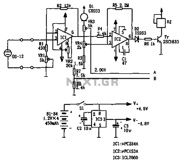
The circuit principle involves an oxygen sensor circuit utilizing the OS-12, a DC amplifier IC1, an A/D converter IC4, a liquid crystal display F2100-34PI, a voltage comparator IC2, and a positive and negative power converter IC, among other components....
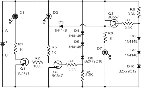
When the battery voltage is 11.5V or lower, transistor Q1 is activated, causing LED D1 to illuminate. If the battery voltage is between 11.5V and 13.5V, transistor Q2 is activated, resulting in LED D2 lighting up. At a battery...
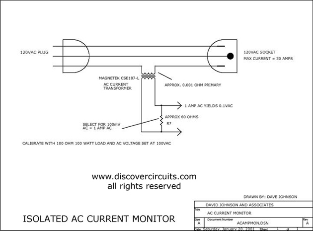
This circuit utilizes a small AC current transformer from Magnetek to generate an isolated voltage that is proportional to the AC current flowing through the primary winding. The AC current transformer operates on the principle of electromagnetic induction, where the...
The objective of this project was to monitor power consumption in a residential setting. In addition to tracking total usage, the goal was to separately monitor and compare the usage of major appliances, such as the water heater, heat...
This is a circuit diagram for a fuse monitor circuit indicator. This very simple circuit utilizes only two components: a single resistor and an LED. This circuit provides a visual indication when the fuse has blown. LED1 typically remains...
This application note describes the creation of a heart rate monitor utilizing an infrared (IR) LED and a phototransistor pair, with the waveform observed at the output of the phototransistor. The purpose of this project is to demonstrate a...