
Three-phase six-step motor control circuit diagram composed of MC33035

The three-phase full-wave six-step motor controller circuit is designed to efficiently manage the operation of an open-loop motor. The PNP Darlington transistors serve as the primary power switches, providing high current gain and facilitating the control of larger currents necessary for motor operation. The inclusion of N-channel power MOSFETs as lower power switches is critical due to their high efficiency and fast switching capabilities, which contribute to the overall performance of the circuit.
Each transistor within the circuit is equipped with parasitic clamping diodes. These diodes are essential for managing the inductive kickback generated by the stator coils during operation, allowing the energy to be returned to the power supply rather than dissipating as heat. This feature enhances the efficiency of the motor controller and prolongs the lifespan of the components.
The circuit's output configuration allows for flexibility in connecting the stator windings. By supporting both triangular and star configurations, the circuit can adapt to various motor designs and application requirements. The option to connect to a Y-neutral ground further enhances the circuit's versatility, enabling it to operate effectively under different electrical conditions.
In operation, at any rotor position, only one power switch from each totem pole is activated, ensuring that the circuit maintains optimal control over the motor. This selective switching allows for the efficient management of current flow through the stator windings, facilitating two-way or full-wave current operation. Such control is vital for achieving smooth motor performance and minimizing vibration.
To address the issue of leading edge spikes in the current waveform, which can lead to limiting errors and affect the performance of the motor, a peak RC filter is incorporated into the design. This filter effectively smooths out transient spikes, ensuring a more stable current detection input. The use of a low sense resistor (Rs) further assists in reducing these spikes, enhancing the reliability and accuracy of the current sensing mechanism within the circuit.
Overall, this three-phase full-wave six-step motor controller circuit is a sophisticated solution for driving open-loop motors, combining effective power management with adaptive output configurations and robust spike suppression techniques.Fig application circuit is a three-phase full-wave six-step driving an open loop motor controller circuit connection diagram. Wherein the power switching transistor Darlington PNP type, the lower power switching transistors are N-channel power MOSFET. Since each device contain a parasitic clamping diodes, which can power the stator inductive energy returned. The output can drive triangular connection or star connection of the stator, if using a separate power supply, but also to drive the Y-connected neutral ground.
At any given rotor position, the circuit shown in Figure 3 are the only one at the top and bottom power switches (belonging to different totem poles) is valid. Thus, through the rational allocation can switch the stator windings from the power supply to ground at both ends, and allows two-way or full-wave current.
Since the leading edge spikes usually occur in the current waveform, and will result in limiting errors. Therefore, the class can be suppressed by the peak RC filter in series with a current detection input.
Meanwhile, Rs low sense resistor also help reduce spikes.
Related Circuits
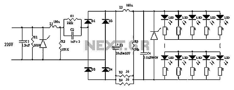
Circuits C1, R1, varistors, L1, and R2 form a filter circuit that includes a primary power supply capable of filtering out transient overvoltage inputs. The circuit also consists of C2 and R2, with additional components C3, C4, and L2....
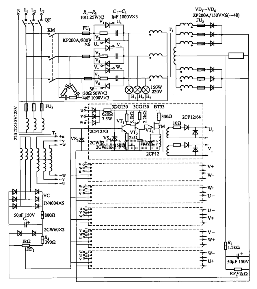
A three-phase thyristor power regulator circuit designed for plating applications, capable of handling currents from 1200A to 6000A at a voltage of 10V. The circuit comprises a main circuit, a trigger circuit, synchronous power components, and a voltage negative...
Pump prime connector, power distribution cell, fuel pump and sender, dual tanks, fuel pump balance relay, vehicle control module, underhood fuse relay, ECM fuse. The described components are integral to the operation and management of a fuel system in a...

This is a simple water level alarm circuit made using a 555 timer IC. The circuit will produce an alarm when the water level reaches a preset level. The water level alarm circuit utilizing a 555 timer IC is designed...
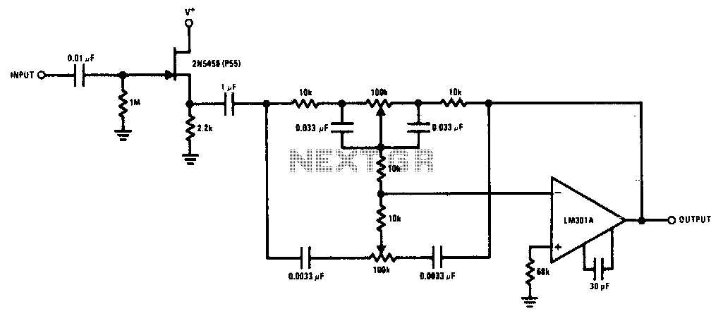
The 2N5458 JFET offers high input impedance and low noise characteristics, making it suitable for buffering an operational amplifier feedback tone control circuit. The 2N5458 is a Junction Field Effect Transistor (JFET) known for its superior electrical characteristics, particularly in...
This door open alarm electronic project is designed using a linear hall effect device and a 555 timer circuit. The project utilizes the TL3103 linear hall effect device for detecting the angle of rotation. The TL3103 is positioned within...