
Thumbwheel programmable interval timer

The programmable timer circuit operates by utilizing a microcontroller that processes the input from the six BCD-encoded thumbwheel switches. Each thumbwheel switch corresponds to a specific digit in binary-coded decimal format, allowing for precise timing settings ranging from seconds to hours. The three SPST switches serve as mode selectors, enabling the user to define whether the input timing is interpreted as seconds, minutes, or hours.
The microcontroller's firmware is designed to interpret the BCD inputs and convert them into a time duration that controls the relay outputs. The three relay-switched outputs are operated based on the programmed durations, allowing for sequential or simultaneous activation of connected devices. The first output is activated for the time set by the first thumbwheel switch, the second output for the duration set by the second thumbwheel switch, and the third output remains active for the total duration of both the first and second outputs.
An integral part of the circuit is the LED display, which provides real-time feedback on the countdown process. During operation, the display shows the time remaining until the next relay activation, enhancing user interaction and control. The design eliminates the need for battery backup due to the nonvolatile nature of the data input via the thumbwheel switches.
In summary, the circuit is designed for reliability and ease of use, providing a versatile solution for timing applications without the complications of volatile memory or battery dependence. This programmable timer is suitable for various applications, including automation systems, industrial controls, and home automation projects.Switch programmable on/off or interval timer, has three relay-switched outputs. Output one is active for the duration of time 1, output two is active for the duration of time 2, and output three is active for the duration of both one and two. Timing data is input through 6 BCD-encoded thumbwheel switches. Three SPST switches inform the WD-55 to interpret this data as NNN seconds. NNN seconds, NNN minutes, or NNN hours The LED display will show the time remaining and the countdown when operating. Since the data is input through switches, the display may be deleted. Also, since the timing information is read from switches, the data is nonvolatile and no battery backup is required.
Related Circuits
The sections available in this datasheet cover general design considerations for the 555 timer, frequently asked application questions (FAQ), design formulas, and examples of innovative applications. Examples of applications include a Missing Pulse Detector, Pulse Width Modulation (PWM), Tone...
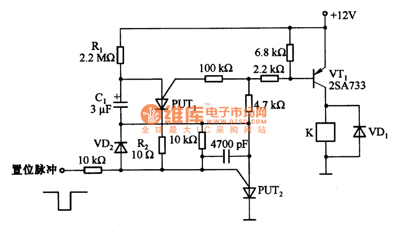
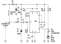
Figure 1 illustrates an enhanced trigger timing circuit that utilizes two Programmable Unijunction Transistors (PUTs). When a set signal is applied, the circuit is activated, causing transistor VT1 to enter the conduction state and energizing relay K. This action...
The typical BPM range for music is between 40 and 240 BPM, corresponding to periods of 1500 ms and 200 ms, respectively. A BPM of 120 equates to a period of 500 ms. The circuit requires a resistor R4...

The circuit depicted in the figure comprises a PGA103 programmable gain instrumentation amplifier. This design utilizes the PGA205 and PGA103 in a cascading configuration, resulting in a total gain for the amplifier. The gain is determined by the product...
This document provides an overview of a simple circuit diagram for frequency (F and V) voltage conversion. It describes a digital frequency meter circuit primarily based on the LM555 timer IC, which is commonly used in various applications, including...

This 555 timer circuit temperature monitoring system project can monitor temperature at up to four points. The system allows for the selection of whether the alarm should be triggered when the temperature increases or decreases, depending on the resistance...