
alarm door bell circuit using ne555 part 1

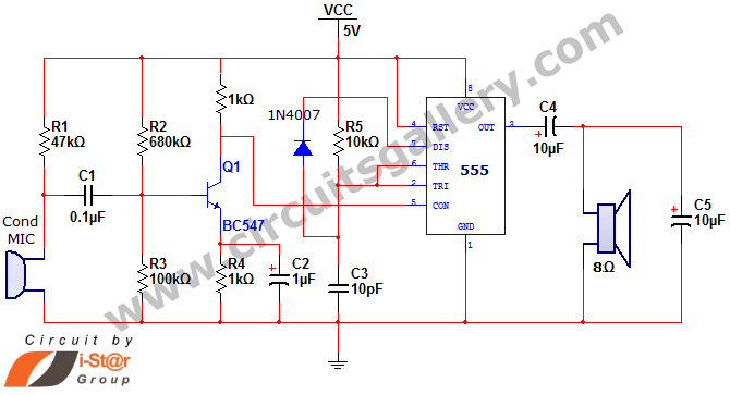
This doorbell circuit utilizes two NE555 timer ICs to create a simple yet effective signaling mechanism. The first timer, configured in monostable mode, is responsible for generating a pulse when the switch S1 is activated. This switch acts as a momentary contact, allowing the circuit to respond only when pressed.
Upon activation, the monostable multivibrator (IC1) produces a high signal for a predetermined duration, which is set by an external resistor and capacitor connected to the timer. The output of IC1 is connected to a loudspeaker, which generates the bell tone. The duration of the sound can be adjusted by changing the values of the resistor and capacitor, providing flexibility in the length of the audio signal.
The second NE555 timer (IC2) can be utilized for additional features, such as creating a visual indicator (e.g., an LED) that illuminates when the doorbell is pressed or for controlling the volume of the sound output. This timer can be configured in astable mode to produce a continuous tone or to modulate the sound output for different effects.
The circuit should be powered by a suitable DC power supply, typically ranging from 5V to 15V, depending on the specifications of the NE555 timers and the loudspeaker. Proper attention should be given to the power ratings of the components to ensure reliable operation.
Overall, this doorbell circuit design is straightforward, making it an excellent project for beginners in electronics, while also offering possibilities for customization and expansion for more advanced users.The main part of this doorbell circuit are two NE555 timer ICs. When some one presses switch S1 momentarily, the loud speaker sounds a bell tone as long as the time period of the monostable multivibrator built around IC1. 🔗 External reference
Related Circuits

The TEA5764UK is a single-chip, electronically tuned FM stereo radio that includes a Radio Data System (RDS) and Radio Broadcast Data System (RBDS) demodulator, along with an RDS/RBDS decoder. This device is designed for portable applications and features fully...
The Sun-Up Alarm can be used to provide an audible alarm for when the sun comes up or it can be used in a dark area and detect when a light comes on. It can also be used to...
This document discusses a simple project utilizing the 555 timer IC. The 555 timer IC can be configured as an audio amplifier using an astable multivibrator configuration. It performs pulse width modulation (PWM) on an audio signal. The current...

One of the most effective communication methods to be implemented in a digital system is the use of the RS232 serial line. The microcontroller 89S51 is equipped with a UART, allowing it to perform serial communication at RS232 levels...

A high voltage power supply DC converter that operates between 3V to 500V has been suggested for use with Geiger tubes. However, during simulation, the output remained at nearly 9V, which matches the input voltage. The schematic drawn has...

The inverter described in this text utilizes a MOS field-effect transistor and a standard power transformer. Its output power is determined by the capabilities of both the MOS field-effect transistor and the transformer, eliminating the need for complex voltage...