
Time base using a delay circuit touch lamp

The NFA.55 timebase circuit delay type light touch switch is designed to replace traditional mechanical switches with a modern, efficient solution. This circuit utilizes a combination of resistors, capacitors, and semiconductor devices to achieve its functionality. The NE555 timer IC serves as the core of the timebase circuit, providing precise timing capabilities that allow for the delay feature of the switch.
Upon initial activation, the circuit remains in a stable state, with the thyristor VT1 in a non-conducting state, preventing the lamp E from lighting. The touch-sensitive electrode sheet M is strategically placed to detect user interaction. When the user touches M, a small leakage current flows through resistor R, which biases diode VT2 into conduction. This action triggers the NE555 timer by sending a negative pulse to its input, effectively starting the timing sequence.
The output of the NE555 timer raises the gate potential of thyristor VT1, allowing it to conduct and power the lamp E. The rapid discharge of the stored charge through VT2 ensures that the circuit responds quickly to the touch, providing immediate feedback in the form of light. Once the touch is removed, VT2 turns off, and the circuit begins to reset. The charging time constant dictated by R and C determines how long the lamp E remains lit after the touch is released.
The design also incorporates safety features, ensuring that the power rating of the connected load does not exceed 40W, which protects the components from overheating and potential damage. This thoughtful design allows for a seamless integration into existing systems, providing an effective solution for modern lighting control while maintaining compatibility with traditional wiring setups.Using a wire connection, use NFA.55 timebase circuit delay type light touch switch, it can directly replace ordinary mechanical switch, without having to change the original interior wiring. The circuit is powered back with good hoof Chapter 96 cases, especially on} U F is lit or put out the lights off, the circuit can always output a voltage fiV steady stream education for state-based circuit NF, 155 electricity. Usually, NE5ji in a stable state, feet lose thirty low grain lrril tube VT1 shake the f J is R, the wear of the clamp level, VTI curse off, the lamp E does not shine.
When the hand touch the electrode sheet M, the body leakage current through R, Wang injection diode VT2 base enables rapid VT2 conduction, which is equivalent to the trigger terminal feet NE555's input a negative pulse, time base circuit busied, foot jump into supplier level. Therefore, the thyristor VT1 gate potential elevation, VT1 get the trigger voltage and Ji Tong, E powered lamp light.
At the same time, G stored charge through VTZ fast relief. After leaving the people at M, VT2 off recovery, 6V DC power on by R; the G Free electricity, so f, both ends of the potential rising. When rose 2 / 3VDO That 1V, when the base circuit is reset, pin restore low, wri lost trigger voltage when the AC zero crossing that is turned off, the lamp E goes out.
In addition to the delay time of the circuit R. , C, has a charging time constant curse, but also by the length of time there is a touch off. When a finger touch time than K, G can store sufficient electrical discharge leaning, the "C. charge to 4V asked on the long, corresponding lamp lighting time will be longer. In addition, the load capacity of the circuit but also by steady pressure pipe vs dissipated power constraints, so the bulb E power not more than 40W.
Related Circuits
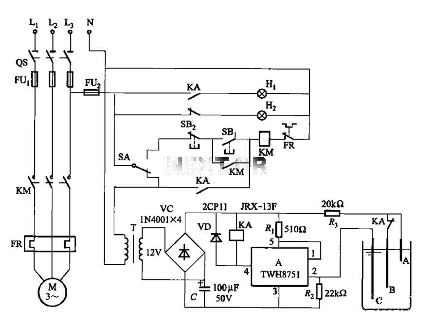
The power switch integrated circuit A features a straightforward design with high sensitivity, ensuring reliable operation. It is part of an automatic liquid level control circuit. When the water level at electrode B drops below 2 feet (0V), circuit...
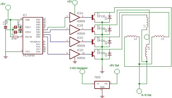
The full wave phase control circuit below was found in a RCA power circuits book from 1969. The load is placed in series with the AC line and the four diodes provide a full wave rectified voltage to the...
Since completing the degree in April, there has been a pursuit for employment. The search has been gradual, but there is optimism for future financial success. In the context of electronic schematics, the pursuit of employment can be likened to...
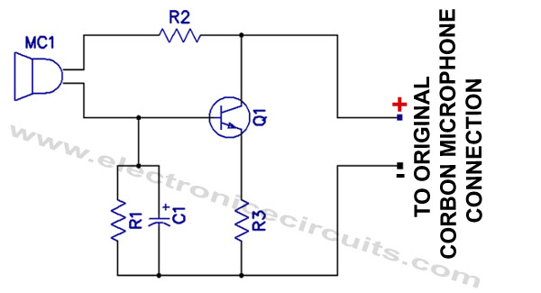
Effective pitching surpasses effective hitting, and a high-quality magnetic microphone outperforms a carbon microphone. This circuit utilizes a single transistor to convert a carbon microphone input into a magnetic microphone output. It is important to note that no ground...
Many amateur receivers are equipped with an S meter that does not operate logarithmically. The proposed circuit is intended to enhance such receivers. Although integrated circuits like the CA3089 or CA3189 are not commonly used today, they play a...
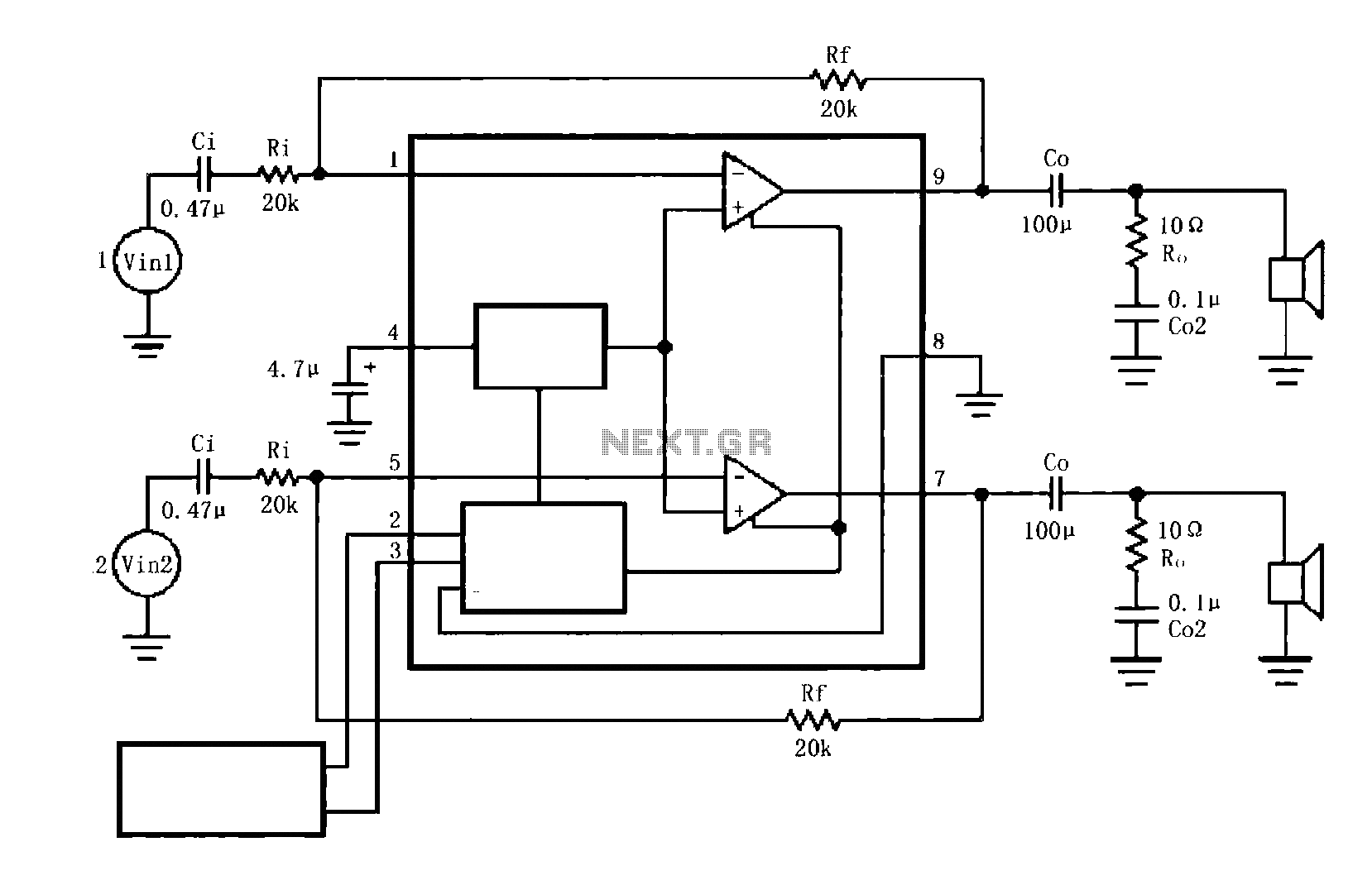
The circuit illustrated is a typical configuration for the LM4916 two-channel amplifier. The left and right channel audio signals are fed into the LM4916, which amplifies them internally. The output is then delivered through a coupling capacitor (Co) to...