
Lamp Dimmer schematic

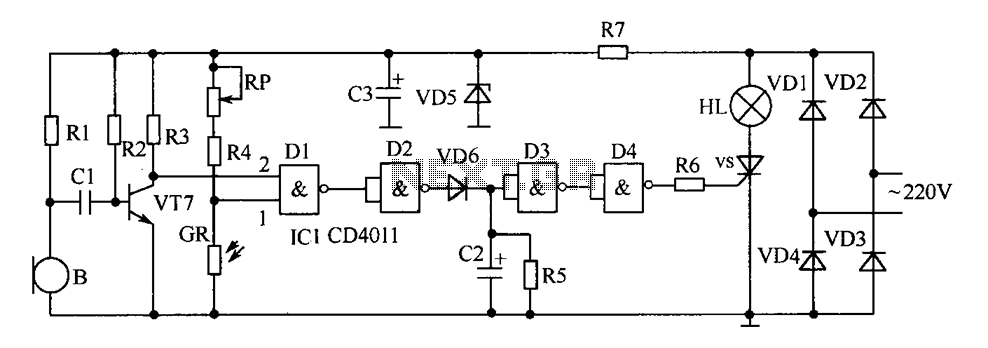
The circuit operates as a phase control dimmer for AC loads, utilizing a full-wave rectification approach to manage power delivery. The four diodes are arranged in a bridge configuration, ensuring that regardless of the AC polarity, the load receives a rectified voltage, which is critical for the SCR's operation. The SCR (Silicon Controlled Rectifier) serves as a controlled switch that allows current to flow through the load once it is triggered by the gate signal.
The timing mechanism is pivotal for controlling the phase angle at which the SCR is turned on. The capacitor (2.2 µF) charges through the 50K potentiometer, and once the voltage across it reaches approximately 8 volts, the small signal transistors switch on. This action discharges the capacitor into the gate of the SCR, turning it on and allowing current to flow through the load for the remainder of the AC cycle.
The adjustment of the 50K potentiometer directly influences the charge time of the capacitor. A lower resistance allows the capacitor to charge faster, thereby triggering the SCR earlier in the AC cycle, which increases the average voltage applied to the load. Conversely, increasing the resistance delays the SCR's triggering, resulting in a lower average voltage across the load.
Furthermore, the 15K resistor serves as a calibration tool, allowing for fine-tuning of the output voltage when the 50K potentiometer is set to its maximum. This feature is essential for ensuring the circuit can accommodate variations in component tolerances, enabling the user to achieve the desired performance without compromising safety or functionality.
It is critical to observe safety precautions when working with AC circuits, as they can pose significant electrical hazards. Proper insulation and handling practices must be followed to prevent accidental contact with live components.The full wave phase control circuit below was found in a RCA power circuits book from 1969. The load is placed in series with the AC line and the four diodes provide a full wave rectified voltage to the anode of a SCR. Two small signal transistors are connected in a switch configuration so that when the voltage on the 2.2uF capacitor reaches about 8 volts, the transistors will switch on and discharge the capacitor through the SCR gate causing it to begin conducting.
The time delay from the beginning of each half cycle to the point where the SCR switches on is controlled by the 50K resistor which adjusts the time required for the 2uF capacitor to charge to 8 volts. As the resistance is reduced, the time is reduced and the SCR will conduct earlier during each half cycle which applies a greater average voltage across the load. With the resistance set to minimum the SCR will trigger when the voltage rises to about 40 volts or 15 degrees into the cycle.
To compensate for component tollerances, the 15K resistor can be adjusted slightly so that the output voltage is near zero when the 50K pot is set to maximum. Increasing the 15K resistor will reduce the setting of the 50K pot for minimum output and visa versa.
Be careful not to touch the circuit while it is connected to the AC line. 🔗 External reference
Related Circuits
The design primarily consists of the ATmega328P-PU microcontroller and an LCD display. Both components necessitate a stable power supply. The ATmega328P-PU microcontroller is an 8-bit AVR microcontroller that operates at a clock speed of up to 20 MHz. It features...
The delay-saving lamp circuit functions as a sound and light control delay energy-saving lighting system. It can directly replace a standard light switch without modifying the existing lighting circuits. In bright or daytime conditions, the sound control feature ensures...

Fluorescent lamps, despite their long presence, remain enigmatic to many individuals due to their complex operational mechanisms. The lamp consists of a gas mixture, primarily containing mercury, which, when energized as an arc, produces a significant amount of short-wave...
This project involved designing an audio amplifier capable of delivering substantial output power with a minimal number of components while maintaining quality. The power amplifier section consists of three transistors and a few resistors and capacitors configured in a...

The following circuit illustrates a Bedside Lamp Timer Circuit Diagram. This circuit is based on the CD4060 integrated circuit. Features: An LED illuminates for approximately 25 seconds. The Bedside Lamp Timer Circuit utilizes the CD4060 IC, which is a versatile...
This circuit is designed to detect incoming calls on a cellular phone, even when the phone's ringer is turned off, by utilizing a flashing LED. The device should be positioned a few centimeters away from the cellular phone, allowing...