
Time Delay Relay

The time delay relay circuit operates on the principle of charging a capacitor through a resistor, which determines the delay period before the relay is activated. The circuit typically includes a momentary push-button switch that, when pressed, initiates the timing sequence.
Upon pressing the button, the capacitor begins to charge through the resistor. The time constant of the circuit, which defines the delay duration, is determined by the formula τ = R × C, where τ is the time in seconds, R is the resistance in ohms, and C is the capacitance in farads. By altering the values of the resistor or capacitor, the delay time can be adjusted to meet specific requirements.
The relay itself acts as a switch that can control a larger load, such as motors or lamps, once the timing period elapses. The relay contacts, which are rated for a certain current and voltage, will close after the capacitor reaches a specific voltage threshold, triggering the load to turn on. The choice of relay is crucial, as it must be selected based on the load's specifications to ensure safe and effective operation.
Additional components may include diodes for flyback protection across the relay coil, preventing voltage spikes when the relay is de-energized. A power supply is also necessary to provide the required voltage for the relay and the timing circuit.
Overall, this time delay relay circuit is versatile and can be implemented in various applications, such as lighting control, motor start delays, or any scenario where a timed activation of a load is desired.When activated by pressing a button, this time delay relay will activate a load after a specified amount of time. This time is adjustable to whatever you want simply by changing the value of a resistor and/or capacitor.
The current capacity of the circuit is only limited by what kind of relay you decide to use. 🔗 External reference
Related Circuits
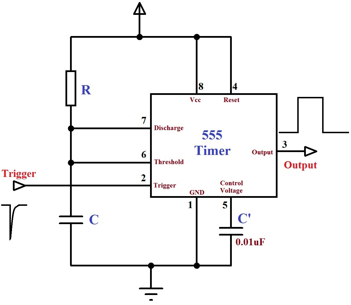
The monostable mode of the 555 Timer operates by having one stable state and switching to an unstable state for a predetermined time period T when triggered. The time period T is determined by the RC time constant in...
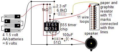
A simple music instrument/keyboard is created using a 555 timer chip circuit, a piece of paper, and a pencil. The project includes a more advanced automatic music player that utilizes a playing head and a long sheet of paper...
The camera has been wired with external shutter leads, and a method is needed to trigger them. These leads must be connected together via a relay at regular intervals, approximately every 2 seconds, starting from launch. A 555 timer...
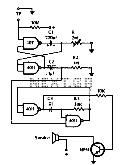
The timer can be utilized for time intervals of up to seven minutes. Activation is achieved by touching the turn-on plate, after which an alarm will sound for a brief duration upon the completion of the selected time, followed...
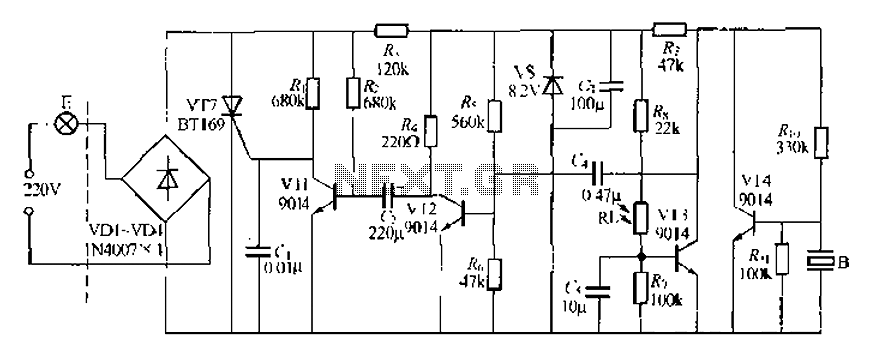
A modified piezoelectric ceramic acoustic-electric transducer is utilized to create a sound and light control system for a stairway walkway with a delay lighting switch. The circuit structure is relatively simple, consisting of diodes VD1 to VD4 and a...
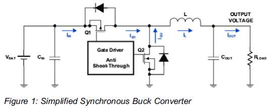
Increased Flexibility for Low-Power Synchronous Buck Converters. Contemporary synchronous buck converters designed for portable applications offer a power-save mode operation to sustain high efficiency throughout the entire range of operation. Modern low-power synchronous buck converters are essential components in portable...