
Timer

The timer circuit is designed for straightforward operation, making it suitable for various applications requiring precise timing. The core of the circuit is a timing mechanism that utilizes resistors (R) and capacitors (C) to establish the desired time intervals and alarm characteristics. The touch plate (TP) serves as a user interface, providing a simple means for activation.
Upon touching the TP, a momentary connection is created, triggering the timer circuit. This initiates a countdown based on the values set by R1 and C1, which are critical for defining the maximum time period of seven minutes. The choice of resistor and capacitor values in this section directly impacts the timing accuracy and range.
For the alarm function, R2 and C2 are instrumental in determining how long the alarm will sound once the timer reaches zero. The relationship between these two components is crucial; increasing either will extend the alarm duration, ensuring that the user is adequately alerted at the end of the timing period.
Additionally, the tonal quality of the alarm is adjustable via R3 and C3. This feature allows for customization of the alarm sound, catering to user preferences or specific application requirements. The interaction between these components can be fine-tuned to achieve the desired auditory signal, with lower resistance or capacitance yielding a deeper tone, while higher values produce a sharper sound.
Overall, this timer circuit exemplifies a blend of simplicity and functionality, making it an effective solution for timing applications in various electronic projects. The design allows for easy modifications to adapt to different timing and sound requirements, enhancing its versatility in practical use.The timer can be used wherever time periods of up to seven minutes duration are needed. To turn on just touch the turn-on plate, and after the selected time has elapsed, an alarm will sound for a short period, then automatically turn off. The turn-on touch plate, labeled TP in the diagram, is made up of two metal strips about 1/16-inch apart.
Bridging the gap with your finger activates the timer. For more time range, increase Rl and/or Cl. R2 and C2 determine the period of time that the alarm will sound Increasing either will extend the time. The tone of the alarm is determined by R3 and C3. Increasing either lowers the tone, decreasing them raises the tone.
Related Circuits
This is a game timer circuit diagram. When the game timer is reset, two actions must occur: the 4017 counter must return to zero, and the 4060... The game timer circuit utilizes the 4017 decade counter and the 4060 binary...
This circuit provides a visual 9-second delay using a 7-segment digital readout LED. When the switch is closed, the CD4010 up/down counter is preset to 9, and the 555 timer is disabled with the output held high. The circuit utilizes...
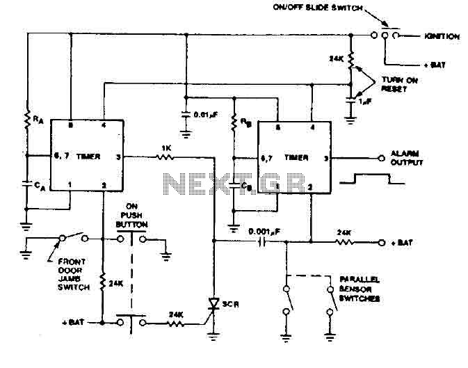
The 555 timer generates a reliable delay, enabling the driver to deactivate the alarm and eliminating the need for an external control switch that could be compromised. Additionally, the RCS prevents the activation of timer B unless it is...
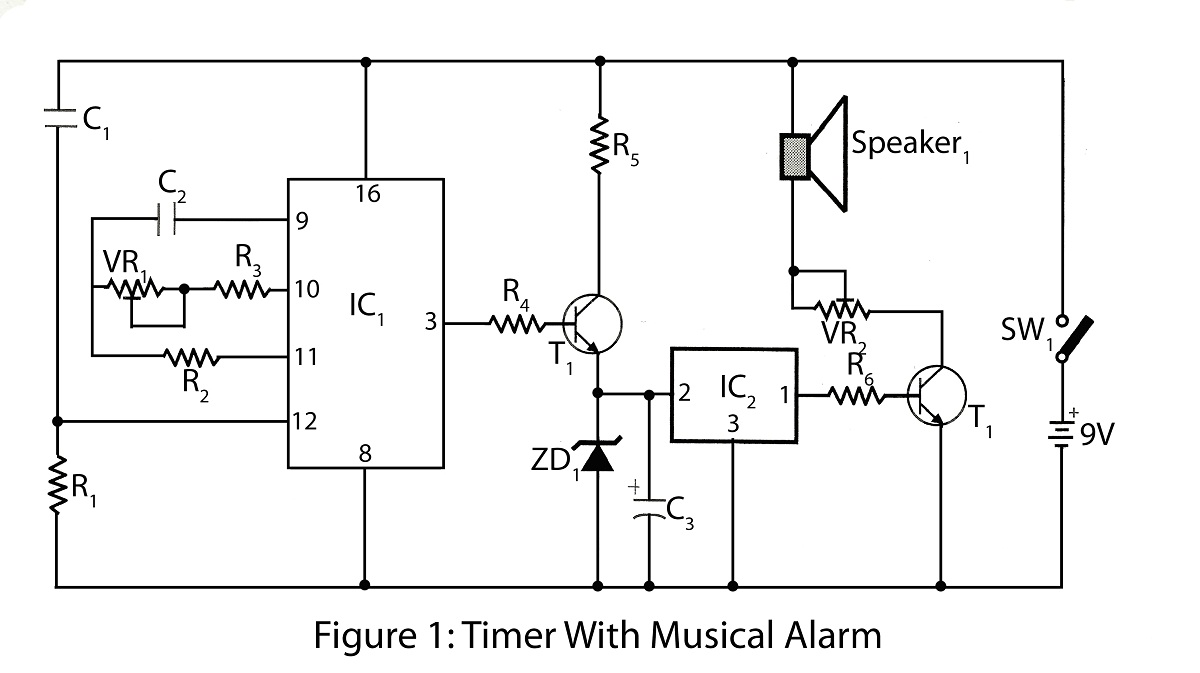
The timer with a musical alarm is an electronic timer project utilizing the CD4060 integrated circuit. It provides a delay ranging from 1 minute to 2 hours. The circuit diagram for the timer with a musical alarm is part...
The two circuits below illustrate the application of the 555 timer to activate a relay for a specified duration by pressing a momentary normally open (N/O) push button. The circuit on the left can be used for longer time...
The output of the transformer has been calculated to be 125 times higher than the input, based on the ratio of 1000 to 8. Given an input of 12V, the expected output should be 1500V, although there is some...