
Time delay relay circuit

The NE/SE555 timer IC is a versatile device widely used in various timing applications, including time delay relays. In this specific circuit configuration, the NE/SE555 operates in monostable mode, where it generates a single output pulse in response to a triggering event. The duration of this output pulse is determined by external resistors and capacitors connected to the timing pins of the IC.
To design the time delay relay circuit, the following components are typically included: the NE/SE555 timer IC, a resistor (R), a capacitor (C), and a relay. The resistor and capacitor values are selected based on the desired time delay. The time delay (T) can be calculated using the formula T = 1.1 * R * C, where R is the resistance in ohms, and C is the capacitance in farads.
The relay serves as the output device, which can control larger loads based on the output from the NE/SE555. When the circuit is triggered, the NE/SE555 sends a signal to the relay, activating it for the predetermined time delay. This feature is particularly useful in applications such as automatic lighting controls, HVAC systems, and industrial automation.
The stability of the NE/SE555 timer against temperature variations is critical for maintaining consistent timing performance. While the stated stability is 0.00, it is essential to consider the operating temperature range and the tolerances of the external components to ensure reliable operation in varying environmental conditions.
In summary, this time delay relay circuit utilizing the NE/SE555 timer offers a reliable solution for time-dependent control applications, leveraging the precision and stability of the integrated circuit to achieve accurate timing functions.This time delay relay circuit is built with IC NE/SE555, produced by Intersil which contains a precision timer. Stability to temperature variations is 0.00. 🔗 External reference
Related Circuits
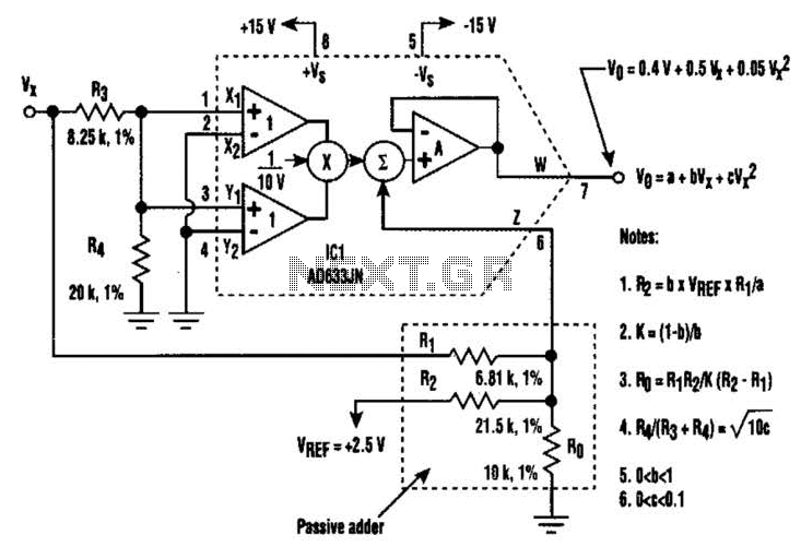
A circuit utilizing a single analog multiplier and five precision resistors can produce an output voltage (Ko) that represents a second-order polynomial. This circuit implements the quadratic function. The input terminals of IC1 are configured to create a positive...
The resistors were not measured precisely, and given their ±5% tolerance, along with a Vref range of 1.2 to 1.3 volts, it is possible to exceed 6 volts in certain scenarios. A discussion arose regarding the effectiveness of these...

This car audio amplifier circuit is based on the LA47536 audio amplifier integrated circuit designed by Sanyo. This audio amplifier circuit is specifically designed for car audio power amplifiers. The LA47536 car audio amplifier IC features four output channels...
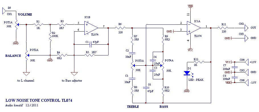
A tone control or pre-amplifier is an amplifier circuit that enhances audio signals. It is important to understand the characteristics, advantages, and disadvantages of various amplifier equipment, as the performance of different amplifiers may not show significant differences. The...
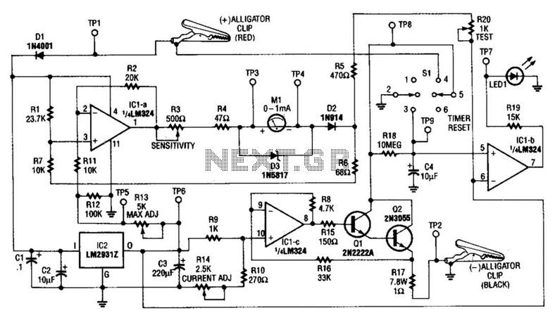
This circuit measures the cold cranking amps of a battery by discharging the surface charge and then assessing the internal resistance. This method provides a more accurate measurement than merely observing the instantaneous voltage drop under load. A constant-current...
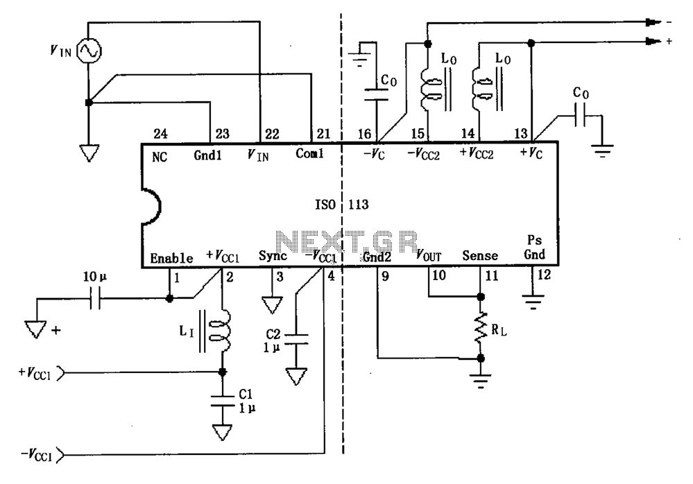
The basic connection circuit for the ISO113 signal and power supply is illustrated. Each power supply terminal must include a bypass filter. If the output current from the isolated power supply exceeds 15mA, it is advisable to utilize an...