
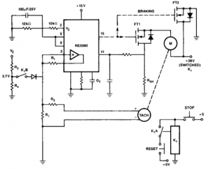
Car alarm circuit using 555 timer

The 555 timer is a versatile integrated circuit commonly used in various timing, delay, pulse generation, and oscillator applications. In this context, the 555 timer is employed to create a delay mechanism that allows for the controlled deactivation of an alarm system. This feature is particularly important in security applications, where the integrity of the system must be maintained without exposing vulnerabilities.
The configuration of the 555 timer can be set up in either monostable or astable mode, depending on the desired functionality. In monostable mode, a single trigger pulse will produce a single output pulse of a defined duration, determined by external resistors and capacitors connected to the timer. This output pulse can be used to deactivate the alarm after a specified delay, providing a window for the driver to safely disengage the system.
Furthermore, the inclusion of a Remote Control System (RCS) enhances the security of the timer operation. The RCS is designed to prevent the triggering of timer B unless certain conditions are met. Specifically, it requires activation through detector switches that are strategically placed, ensuring that unauthorized attempts to trigger the timer are thwarted. This design minimizes the risk of false alarms and enhances the overall reliability of the alarm system.
In summary, the integration of the 555 timer with an RCS in this application not only facilitates a controlled delay for alarm deactivation but also reinforces the security of the system by employing strategic triggering mechanisms. This approach effectively mitigates vulnerabilities associated with external control switches, ensuring that the alarm system remains robust against tampering.555 timer produces a guaranteed delay, allowing the driver to deactivate the alarm and the elimination of a control switch vulnerable outside. The RCS prevents triggering a timer timer B, unless B is triggered by timer switches strategically located detector.
Related Circuits
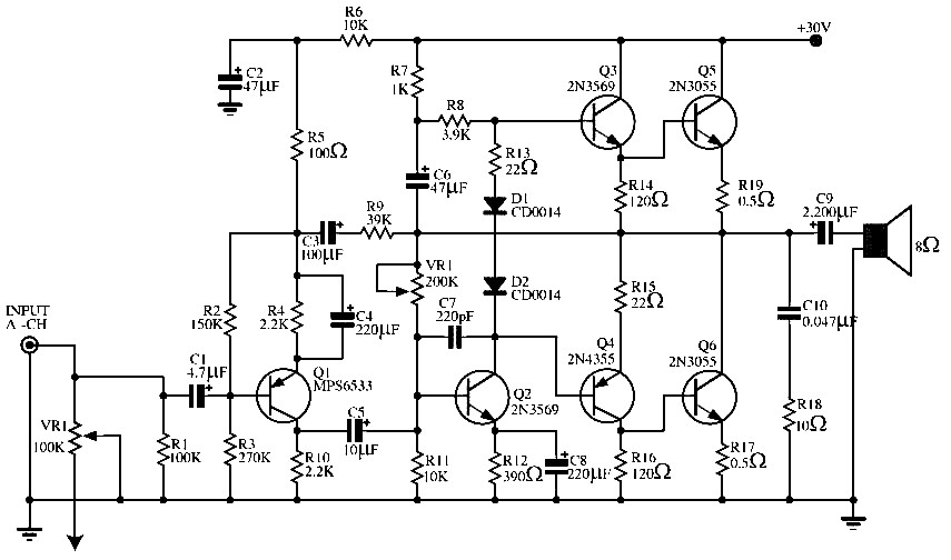
This circuit is useful for creating a constant speed motor control, ensuring that the motor speed remains constant despite variations in load and electrical voltage. The circuit for a constant speed motor control typically employs feedback mechanisms to maintain a...
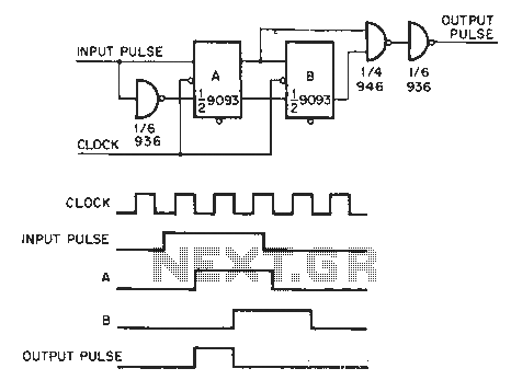
The circuit generates a clock that is synchronized with the pulse width of two clock pulses, producing a random pulse width that is five times the input pulse width of the clock pulse. In the flip-flop circuit, A and...
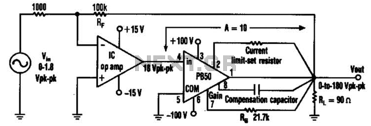
An Apex PB50 Booster Amplifier, along with an integrated circuit (IC) operational amplifier, can be utilized in a high-voltage operational amplifier configuration to convert a small analog signal into a 180-V peak-to-peak signal. Apex Microtechnology produces a variety of...
More: The input data lacks specific content, providing only placeholders without any detailed information. In the context of electronic schematics, a comprehensive description typically involves detailing the components, their interconnections, and the overall functionality of the circuit....
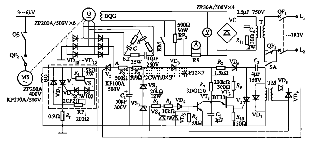
The circuit depicted in Figure 16-105 illustrates a synchronous motor. The components include BQ, which represents its field winding, and G, which denotes the AC excitation for the motor. The notation BQG indicates the field winding, with an empty...
To comprehend the interconnections between the following circuits, it is essential to first review the concept chapter. It is at the discretion of the user to select one or two of these circuits for personal development. The discussion begins...