
Color display circuit

The circuit utilizes a series of transistors to control the brightness of red, green, and blue LEDs, which together create a full spectrum of colors through additive color mixing. The transistors (VT1, VT2, VT3) serve as switches that regulate the current flowing to each LED. The adjustment of the base bias resistors (RP1 and RP4) allows for fine-tuning of the LED brightness, enabling the educator to demonstrate the effects of varying color intensities and the resulting color combinations.
In practical applications, the circuit can be integrated into educational setups where students can interactively learn about color synthesis. By adjusting the resistors, they can observe firsthand how changes in the current affect the brightness of each LED, thereby gaining a deeper understanding of how colors are synthesized in color television technology. This hands-on approach not only enhances learning but also demystifies the technical aspects of color reproduction in electronic displays. Overall, the circuit serves as a valuable educational tool, bridging theoretical concepts with practical demonstrations in the field of electronics and color science. Colour in teaching, in order to allow students to understand the principle of color TV color synthesis. This circuit can be beneficial to use visual teaching, realistic reprodu ction of color signals received good teaching. Thus breaking the color synthesis abstraction. (1) Working principle of the circuit shown in Fig. It is away from the circuit according to the TV imaging using light emitting diode color synthesis circuit. FIG VT1 red light emitting diode driving circuit, VD1 ~ VD3 ultra-high brightness red LED, operating current is provided in terms of o ~ 30mA (depending on the characteristics of the light emitting diode may be), R., RP1 is VT1 base bias resistor, adjusting RP1, can change the flow through the light emitting diode operating current can be changed by a red LED diode emission luminance.
VT2 green light emitting diode driving road. VT3 for the blue light-emitting diode driving circuit, VT4 as a light adjustment circuit. R4, RP4 for the VT4 base bias circuit. RP4 adjustment (ie adjustment of VT4 collector current), you can change the flow through the red, green and blue light-emitting tube current and, therefore, changes the three color brightness light-emitting tube.
Related Circuits
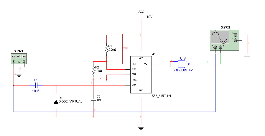
Hello everyone. I need some help. I have constructed a PWM and PPM circuit. The output is functioning smoothly, but I am experiencing some problems and I am not very experienced. The PWM (Pulse Width Modulation) and PPM (Pulse Position...
This circuit allows for the observation of movement between various stroboscopes. The generation of a rectangular signal is accomplished using an NE555 timer. It operates on a low power supply, which is created using a simple transformer (TR1), a...
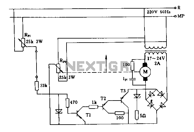
The FIG potentiometer RP2 has a sliding contact that is directly connected to the antenna. The system operates such that only when potentiometers RP1 and RP2 are positioned identically, do the non-conductive transistors and rectifier bridge remain off, resulting...

The robot requires a method for detecting obstacles (or other robots) without making physical contact. This capability allows the robot to determine whether to avoid or confront and investigate the obstacle based on its programming. This document outlines the...
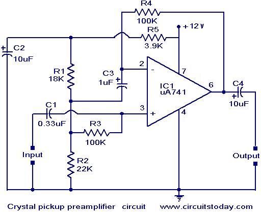
A preamplifier that operates on a single supply and is suitable for high-impedance crystal pickups is presented here. The circuit functions as a non-inverting AC amplifier, with the gain determined by the feedback resistor R4; a smaller R4 results...
This is a circuit which I originally included in my book, 22 Tested Transistor Projects, published by Babani Press in 1976 (ISBN 0 900162 63 S). It is one I had great fun with. It uses the PUT Complimentary...