
pulse timer control relay circuit

The described circuit operates using the popular 555 timer IC, which is widely utilized for timing applications due to its versatility and ease of use. The configuration can be set up in either astable or monostable mode, depending on the desired application. In this instance, it appears to be configured in monostable mode, where the output pulse width is determined by the resistor R1 and a capacitor connected to the timing circuit.
In this configuration, when a trigger signal is applied to the 555 timer, it activates the output pin, which can then control a relay. The relay can switch between the NO and NC contacts based on the output state of the timer. For instance, when the output is high, the NO contact closes, allowing current to flow to the connected device, effectively enabling it. Conversely, when the output goes low, the relay returns to its default state, opening the NO contact and closing the NC contact, thus disabling the device.
The timing period is primarily defined by the resistor R1 and a capacitor (let's denote it as C1) connected to the discharge pin of the 555 timer. The time period (T) can be calculated using the formula T = 1.1 * R1 * C1, where T is in seconds, R1 is in ohms, and C1 is in farads. By selecting appropriate values for R1 and C1, a wide range of timing intervals can be achieved, allowing for flexible control of the connected devices.
Additional components such as diodes may be included in the circuit to protect against back EMF generated by the relay coil when it is de-energized, ensuring the longevity and reliability of the circuit. Furthermore, a power supply suitable for the relay and the 555 timer must be provided to ensure proper operation.
This relay control circuit can be applied in various applications, such as timed lighting systems, automatic irrigation systems, or any scenario where devices need to be activated or deactivated after a predetermined period.Today we would like to offers solutions for a set time for take control relay and take NO. / NC. contact to apply to control other devices. such as disable or enable the device. function of this circuit is using IC555 to determine the pulse and a resistor R1 to the period of time. 🔗 External reference
Related Circuits

The robot requires a method for detecting obstacles (or other robots) without making physical contact. This capability allows the robot to determine whether to avoid or confront and investigate the obstacle based on its programming. This document outlines the...
Build the LC oscillator shown at the bottom of this page for a school project, but there are some challenges in translating the theoretical circuit into a real-world application. The understanding of the circuit's operation on paper is clear....
The opto-isolator LEDs are connected to three wires labeled "FWD," "REV," and "ENA." These wires serve as the interface between the bridge and the microprocessor. It is important to note that there is no "ground" signal present. When connecting...
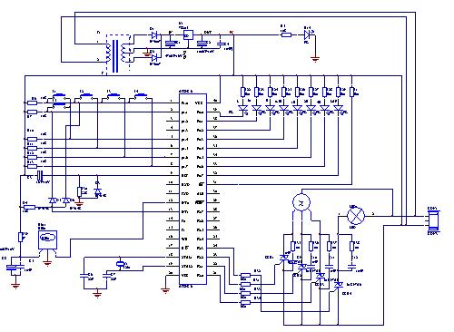
The electric fan with remote control underwent extensive research and development in the Pearl River Delta area of Guangdong during the early 1990s. It utilizes a specialized mask chip that serves as the primary management chip. A systematic scheme...
The UBA2024 is a half-bridge integrated circuit (IC) and a 550 V lamp controller. This device features 9-ohm switches that support standard compact fluorescent lamp (CFL) applications up to 15 W. The UBA2024 is specifically designed for driving compact fluorescent...
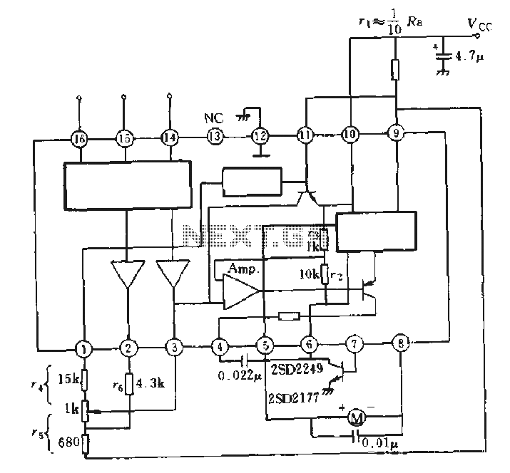
The AN6657 is a 16-pin dual in-line plastic package, while the AN6657S features a 16-pin dual flat plastic package. The speed control function operates with an internal H-bridge driver chip circuit, utilizing pins 5 and 8 for H-bridge driver...