
Timer with buzzer and optocoupler circuit

The circuit operates based on the principle of time measurement using a 4060 IC, which serves as both an oscillator and a frequency divider. The frequency of oscillation is set by the external resistor-capacitor combination, allowing for precise timing applications. The reset function ensures that the timing starts from a known zero point, which is crucial for accurate measurements.
Transistors Q1 and Q2 are used as switches to control the buzzer and the external circuit. When the counter reaches the predetermined count, Q14 outputs a high signal that turns on these transistors, activating the buzzer to provide an audible signal, indicating the end of the timing period. The optocoupler IC2 allows for isolation between the timing circuit and any external loads, ensuring that the timing function remains unaffected by the characteristics of the external circuit.
The adjustable time delay feature is particularly useful for applications requiring variable timing intervals. The use of a potentiometer allows for easy fine-tuning of the timing period, making the circuit versatile for different applications. The power supply options provide flexibility in deployment, whether in portable battery-operated scenarios or fixed installations with a stable external power source.
In summary, this circuit is an efficient solution for applications requiring time measurement and control, with features that allow for both audible feedback and external circuit activation, making it suitable for a wide range of electronic projects.A small circuit that can find a lot applications of measurement time. She has the possibility us inform with sound signal from the BZ1. At the same time, exist the possibility drive a external circuit via the optocoupler IC2, after we connect the applicable circuit in contacts [ A ] and [ B ]. The circuit is based on IC1 (4060), which include in h is inside, oscillator and a binary divider of 14 stage. The frequency operation of oscillator is determined by a circuit R-C that connected in pins 9, 10, 11 of IC1. We give supply in the circuit, with switch S1, is presented a pulse in 12 [ RESET ] via C1 and R3, null him counter, require the measurement of pulses to begin from the zero.
Than the count get at in 14th digit then exit Q14 in the pin 3, acquire high logic level. This voltage drive the base the Q1-2, the transistors turn on, thus buzzer BZ1 sound, also the IC2 is ready to drive, via contacts [ A][B ], any suitable external circuit. The time delay is regulated with the potesometer RV1, in time delay that begin from 1 minute up to 2 hours, proportionally with the combination of prices that they will have the RV1 and C2.
[ see Table ]. The circuit can be supplied from a battery 9V or from external supply. Led D1 and R4, we can him cut out, they do not affect the circuit, simply us it show that the circuit work. The requirement in current when the circuit make time count, are not big (1mA roughly), with the D1 in circuit, on the contrary when activated output Q14, then the requirements in current boost, proportionally the materials that are activated [ D1, BZ1, IC1 ], reaching roughly 40mA.
🔗 External reference
Related Circuits
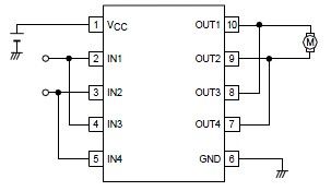
A simple forward-reverse motor control driver electronic circuit can be designed using the LB1948M, a two-channel low saturation voltage forward-reverse motor control driver IC. The LB1948M motor driver is suitable for use in 12V system products and can drive...
The following circuit illustrates an Ultrasonic Sensor Switch circuit diagram. This circuit is based on the 555 Timer IC for the Ultrasonic Transmitter. The Ultrasonic Sensor Switch circuit utilizes a 555 Timer IC configured in astable mode to generate ultrasonic...
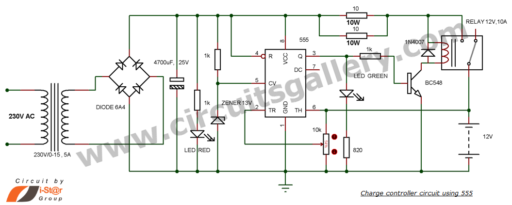
This is a simple DIY charge controller schematic created in response to a request from one of the readers on our Facebook page. The primary component of this automatic battery charger circuit is a 555 timer, which compares the...
Input J4 features an offset function that is activated only when no plug is inserted into J4, as the switching contact of J4 connects to the positive supply voltage through the protection resistor R8. The inverting sum of all...
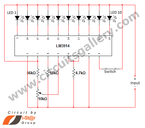
In various situations, it is necessary to indicate the amount of battery charge using methods such as LED dot displays or LED bar displays. This circuit utilizes the LM3914 integrated circuit to serve as a battery charge indicator with...
A simple thermostat circuit that can control a relay to supply power to a small space heater through the relay contacts. The relay contacts must be rated above the current requirements for the heater. Temperature changes are detected by...