
Timer with alarm

The described circuit is a timer that operates within two distinct time ranges, providing flexibility for various applications. The first range allows timing from 10 seconds to 5 minutes, suitable for short-duration tasks, while the second range extends from 1 minute to 80 minutes, accommodating longer timing requirements.
Powering the circuit with a 9-V battery ensures portability and ease of use, making it ideal for applications where access to mains power is limited. The LED serves as a visual indicator of the timer's operation, flashing at a frequency that is consistent regardless of the selected timing range. This feature enhances user feedback, allowing for easy monitoring of the timer's status.
The reset functionality provided by switch S2 is critical for the operation of the circuit. When S2 is closed, the timer resets to its initial state, allowing the user to start a new timing cycle. This ensures that the timer can be reused for multiple tasks without the need for manual intervention or disconnection from power.
In terms of component selection, the circuit may include a timer IC, resistors, capacitors, and the LED. The timer IC is responsible for generating the timing intervals based on the chosen range, while the resistors and capacitors will set the timing characteristics. The circuit design should account for the LED's forward voltage and current specifications to ensure proper operation without exceeding the component ratings.
Overall, this timer circuit design is efficient, user-friendly, and versatile, making it suitable for various timing applications in both hobbyist and professional settings.The circuit has two ranges: 10 sees to 5 mins and 1 min to 80 mins. It can be powered by a 9-V battery. With the LED connected as shown a reasonable frequency of flashing occurs throughout the range of operation. This circuit is reset when S2 is closed.
Related Circuits
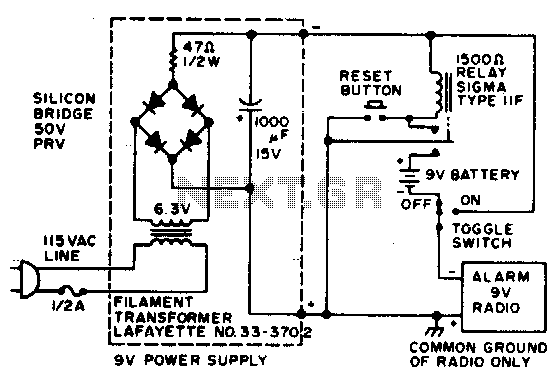
In the event of a power failure, the radio alarm activates without producing a loud siren, bell, or whistle. The alarm remains active even after power is restored and will continue until the RESET button is pressed. The described circuit...
This circuit is designed to power a lamp or other appliance for a specified duration of 30 minutes, after which it automatically turns off. It is particularly useful for nighttime reading, as it can turn off a bedside lamp...
This document presents an improvised circuit model designed to eliminate unwanted DC offset voltage from the output, which affects previously discussed circuits. All prior circuits were intended as low-power Class D amplifier sources suitable for driving headphones through a...
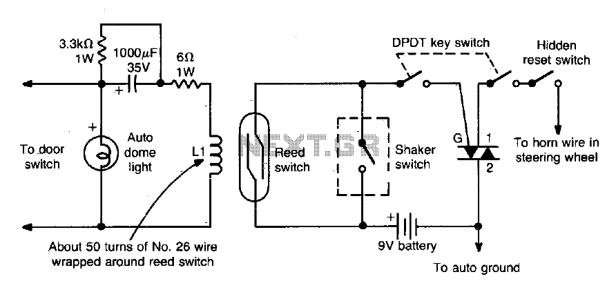
The dome light current flowing through LI closes the reed switch and activates the alarm. Additionally, a shaker switch can also trigger the alarm. The circuit operates by utilizing a dome light that is connected to a current source, designated...
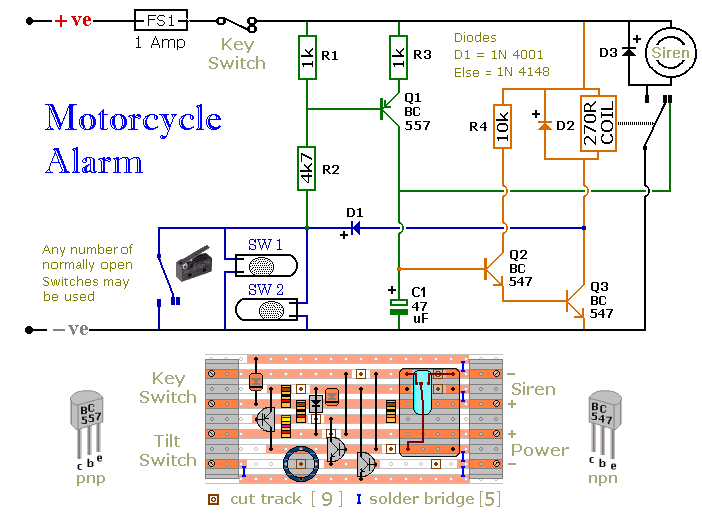
Any number of normally open switches may be used. Fit the mercury switches so that they close when the steering is moved or when the bike is lifted off its side-stand or pushed forward off its centre-stand. Use micro-switches...
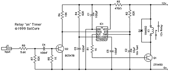
This circuit includes a Relay Timer Circuit. One of the most commonly used circuits is that of the 555 Timer integrated circuit (IC). The circuit is designed to control a relay based on a timing interval. The Relay Timer Circuit...