Power failure alarm

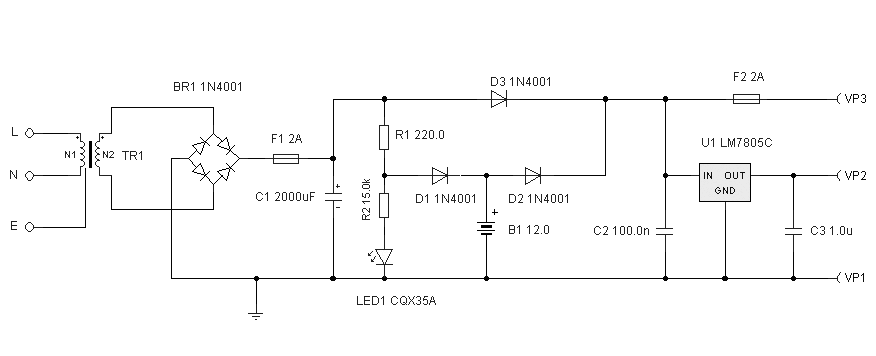
In the event of a power failure, the radio alarm activates without producing a loud siren, bell, or whistle. The alarm remains active even after power is restored and will continue until the RESET button is pressed.
The described circuit functions as a power failure alarm system, designed to alert users of a loss of electrical supply without the use of intrusive sound signals. The core of the system includes a power monitoring unit that detects when the mains power is lost. Upon detection, the system triggers a low-power radio alarm, which can be a simple audio output device that emits a soft tone or a visual indicator, such as an LED light, to notify the user.
The system is equipped with a latching mechanism that keeps the alarm engaged even after power is restored. This is typically achieved using a flip-flop circuit or a microcontroller programmed to maintain the alarm state until a manual intervention occurs. The RESET button serves as a manual override, allowing the user to deactivate the alarm once they have acknowledged the power failure.
To enhance the functionality of the circuit, it may include additional features such as a battery backup for the alarm system, ensuring that it remains operational during a power outage. Furthermore, the circuit design should incorporate protection against power surges when the supply is restored, potentially using components such as diodes or fuses.
The overall schematic would typically consist of a power supply section, a detection circuit, an alarm output stage, and a reset mechanism, all interconnected to provide a reliable and user-friendly power failure alert system.If the power fails, the radio alarm goes on. No loud siren, bell, or whistle Even if the power is restored, the alarm stays on until RESET button is pushed.


