
Relay Timer Circuit With 555 Timer IC

The Relay Timer Circuit utilizing the 555 Timer IC is a versatile and widely employed configuration in various applications, such as automation systems, delay timers, and control systems. The 555 Timer can operate in either monostable or astable mode, depending on the desired functionality.
In monostable mode, the circuit generates a single output pulse in response to a trigger input. The duration of this pulse is determined by the resistor-capacitor (RC) time constant, which can be adjusted to set the timing interval. The relay is activated when the output of the 555 Timer goes high, allowing current to flow through the relay coil, thus closing the relay contacts and enabling the connected load.
In astable mode, the 555 Timer continuously oscillates between its high and low states, producing a square wave output. This configuration can be used for applications requiring periodic relay activation, such as flashing lights or signal generators. The frequency of oscillation is determined by the values of two resistors and a capacitor connected to the 555 Timer.
Key components of the circuit include the 555 Timer IC, resistors, capacitors, and the relay. The relay should be selected based on the load requirements, ensuring that it can handle the necessary voltage and current. Additionally, protective components such as diodes may be included to prevent back EMF from damaging the circuit when the relay is deactivated.
Overall, the Relay Timer Circuit with the 555 Timer IC is an effective solution for implementing timed control in electronic systems, providing flexibility and ease of use for various applications.This circuit bellow include in the Relay Timer Circuit. One of the most commonly used circuits is that of the 555 Timer I.C. The circuit is .. 🔗 External reference
Related Circuits
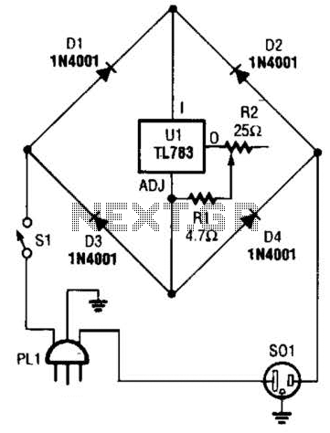
A current control circuit for temperature regulation of a soldering iron utilizes a high-voltage integrated regulator, TL783 (U1). With the specified component values, this circuit is suitable for use with a soldering iron rated at 25 W or less. The...
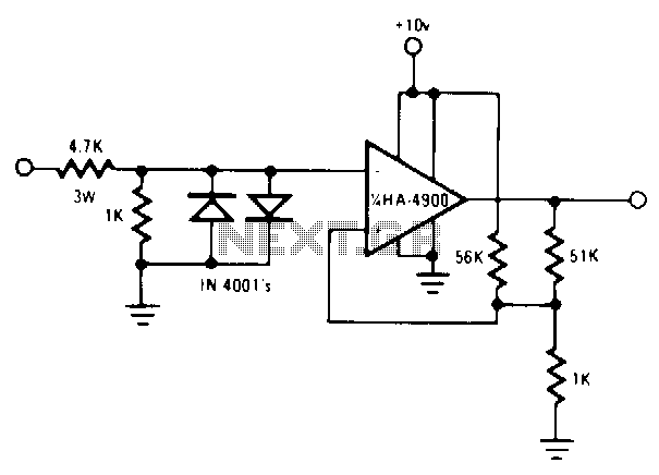
Here is a handy zener diode tester which tests zener diodes with breakdown voltages extending up to 120 volts. The main advantage of this circuit is that it works with a voltage as low as 6V DC and consumes...
Utilize a pair of Maxim's 5V-powered MAX231 RS-232C transmitters as drivers to achieve a dual-color LED. These transmitters necessitate only a single-ended, 5-V input to internally generate ±10 V. Their outputs are designed to be short-circuit-proof and can provide...

Automatic electronic refrigerator deodorant sterilization circuit The automatic electronic refrigerator deodorant sterilization circuit is designed to eliminate odors and sterilize the interior of a refrigerator. This circuit typically employs a combination of sensors, microcontrollers, and sterilization techniques to achieve effective...
A basic square wave generator has been designed to operate a speedometer circuit board, which is responsible for controlling various functions. The square wave generator circuit typically consists of a few key components: a timer IC, such as the 555...
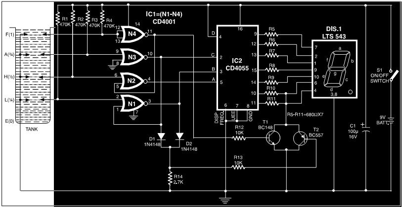
This circuit is a fluid level indicator that displays each level using meaningful English letters. It employs a seven-segment display to represent the letters E for empty, L for low, H for half, A for above average, and F...