
tl062 subwoofer low pass filter

The low-pass filter circuit designed for subwoofers effectively attenuates frequencies above a specified cutoff, ensuring that only the desired low-frequency signals are amplified and sent to the subwoofer. The use of the TL062 op-amp is particularly advantageous due to its high input impedance, which minimizes loading on the preceding stages of the audio signal path.
In the first stage, the configuration allows for the mixing of left and right audio channels. The inverting input of IC1a receives signals from both channels, providing a balanced output that is crucial for stereo audio applications. The gain control implemented with potentiometer R3 allows for fine-tuning of the signal level before it is passed to the filtering stage, allowing for customization based on the specific requirements of the subwoofer and the audio system.
The second stage features a filter network composed of resistors R5, R6, R7, R8, and capacitors C4 and C5. This network is designed to create a low-pass filter characteristic, where the cutoff frequency can be determined by the values of these components. The design ensures that high-frequency signals are effectively attenuated, preventing them from reaching the subwoofer, which is optimized for low-frequency reproduction.
The buffer stage provided by IC1b serves to isolate the filter output from subsequent stages, ensuring that the filtered signal remains stable and unaffected by varying loads. The output at pin 7 of the TL062 is the final low-frequency signal, ready to be amplified by the subwoofer amplifier, thus delivering a rich and deep bass response essential for an immersive audio experience. This circuit exemplifies a practical approach to integrating a low-pass filter within a subwoofer system, leveraging the capabilities of the TL062 op-amp to achieve high-quality audio performance.Many low pass filter circuits for subwoofer seem to be given And this is also just Another one. The circuit given here is Depending about the opamp TL062 from one ST Micro electronics. TL062 is really a dual high input impedance J-FET opamp And this has quite low power consumption and high slew rate. The opamp has great audio characteristics and it`s quite suitable for this circuit. Out of those two opamps inside TLC062, initial one is wired as the mixer cum pre amplifier stage. The left and right channel seem to be connected in towards the inverting input of IC1a for mixing. The gain of initial stage seem to be either adjusted using POT R3. The output of those initial stage is connected in towards the input of second stage throughout the filter network comprising of components R5, R6, R7, R8, C4 and C5. The second opamp (IC1b) serves as a buffer and the filtered output is at the pin 7 of those TLC062. 🔗 External reference
Related Circuits
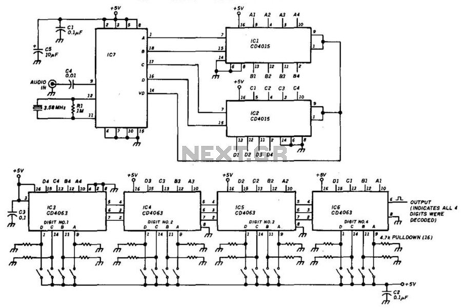
This decoder will respond to a preselected 4-digit DTMF number. IC7 is a Radio Shack IC device (part #276-1303). The logic is all CMOS. The digits are selected by SW1 and SW2, a pair of 8-position DIP switches. The described...
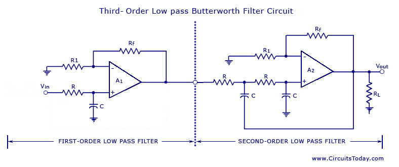
From the discussion made so far on the filters, it can be concluded that in the stopband, the gain of the filter changes at the rate of 20 dB/decade for first-order filters and 40 dB/decade for second-order filters. This...
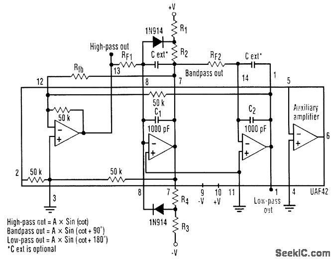
A three-phase sine-wave oscillator can be constructed using a single UAF42 state variable filter, along with a few resistors and diodes. The circuit provides three output nodes: high-pass output, bandpass output, and low-pass output. The signals at the bandpass...
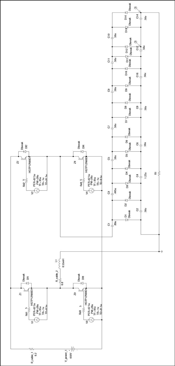
Thesis by Rafael Bräg at the University of Canterbury, New Zealand, in cooperation with the Universität Karlsruhe, Institut Elektrotechnik und Hochspannungstechnik. The thesis presents a comprehensive study conducted by Rafael Bräg, focusing on advancements in the field of electrical engineering....
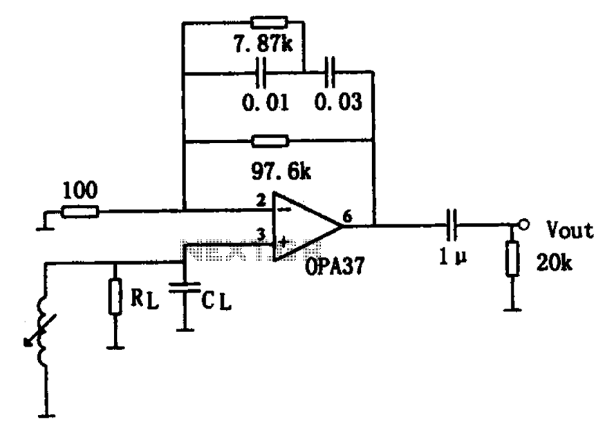
The OPA37 serves as a low-noise preamplifier. The input signal is connected to the inverting input of the OPA37 (pin 3), while the circuit components RL and CL represent the load impedance for electromagnetic pickups. The resistance and capacitance...
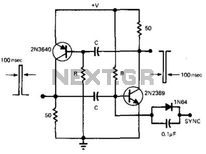
This simple and symmetrical free-running generator has a 50-ohm output impedance, a pulse width of 100 ns, and complementary outputs that swing from ground to the power supply voltage. It operates within a power supply range of less than...