
TL497A Voltage Converter

The TL497A is a versatile voltage regulator that operates in both step-up (boost) and step-down (buck) configurations. In this specific application, the circuit is configured as a boost converter, allowing it to increase the voltage level efficiently. The design typically includes essential components such as inductors, diodes, capacitors, and feedback resistors to stabilize and regulate the output voltage.
The operation begins when the input voltage is applied to the circuit. The TL497A uses a control loop to monitor the output voltage and adjust the duty cycle of the switching signal to the power transistor, which drives the inductor. As the inductor stores energy, the circuit periodically switches the transistor on and off, allowing the energy to be transferred to the output capacitor. This process results in a higher voltage being delivered to the load.
Key parameters to consider in the design include the selection of the inductor value, which affects the current ripple and efficiency, as well as the output capacitor, which smooths the output voltage. Additionally, the feedback network must be carefully designed to ensure stability and proper voltage regulation across varying load conditions.
Overall, the TL497A voltage converter provides a reliable solution for applications requiring a stable higher voltage from a lower voltage source, making it suitable for powering devices that operate within the specified output voltage range.This voltage converter is built with TL497A and converts an input voltage of 5 12 voltage to a higher level of 15 30 volts. This is specially helpful i.. 🔗 External reference
Related Circuits
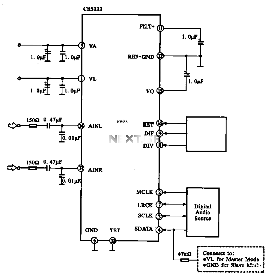
Audio A/D converter circuit configuration using the CS5333 chip, which is a high-performance 24-bit, 96 kHz stereo A/D converter commonly used in digital products. This circuit converts one or more audio signals into a digital signal for processing and...
A voltage-controlled oscillator (VCO) is an electronic signal generator that produces a signal with a variable frequency, which is dependent on an input voltage level. A voltage-controlled oscillator is a fundamental component in various electronic applications, including phase-locked loops (PLLs),...
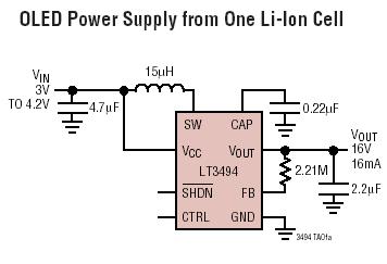
The LT3494 and LT3494A are low-noise boost converters that integrate a power switch, Schottky diode, and output disconnect circuitry. These devices utilize an innovative control technique that results in minimal output voltage ripple and high efficiency across a broad...
The old and omnipresent NE555 can be very good at something it was not meant for: driving relays or other loads up to 200 mA. The picture shows an example circuit: if the input level rises over 2/3 of...
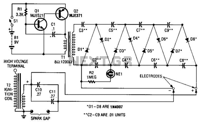
This circuit employs a transistor oscillator and a voltage multiplier to charge capacitors CIO and CI1 to a high voltage. When the spark gap breaks down, T2 generates a high-voltage pulse through the discharge of capacitors CIO and CI1...
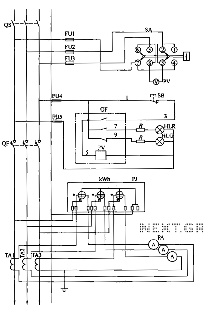
The BSL is illustrated in a low-voltage distribution panel wiring diagram. It consists of three main components: the voltage measuring circuit, secondary circuit protection, and the energy metering circuit. (1) The voltage measuring circuit includes a voltage switch (SA)...