
Voltage Controlled Switch with 555

The NE555 timer IC is a versatile component widely used for timing applications, but it can also control various loads, including relays, effectively. In the described circuit, the NE555 operates in a comparator mode. The input voltage is compared against two reference levels set by the internal voltage divider of the NE555. When the input voltage exceeds 2/3 of the supply voltage, the output at pin 3 transitions high, activating the relay. This action closes the relay contacts, allowing current to flow through the connected load.
Conversely, when the input voltage drops below 1/3 of the supply voltage, the output at pin 3 transitions low, deactivating the relay and opening the contacts. The use of a diode (D1) in the circuit is critical as it protects the NE555 from voltage spikes generated when the relay coil is de-energized. This flyback diode allows the current induced by the collapsing magnetic field of the relay to safely dissipate, preventing damage to the timer IC.
The design can be further optimized by selecting appropriate resistor and capacitor values to tailor the response time and hysteresis of the relay operation. This configuration allows for a stable on/off control of the relay, making it suitable for applications such as switching devices on and off based on varying input signals. Overall, this NE555-based relay driver circuit exemplifies the flexibility of the timer IC beyond its conventional applications.The old and omnipresent NE555 can be very good at something it was not meant for: driving relays or other loads up to 200 mA. The picture shows an example circuit: if the input level rises over 2/3 of the supply voltage - it will turn on the relay, and the relay will stay on until the level at the input drops below one third of the supply voltage.
If the relay and D1 were connected between pin 3 and ground, the relay would be activated when the input voltage drops below one third, and deactivated when the input voltage goes over two thirds of the supply voltage. It is also a nice advantage that 🔗 External reference
Related Circuits
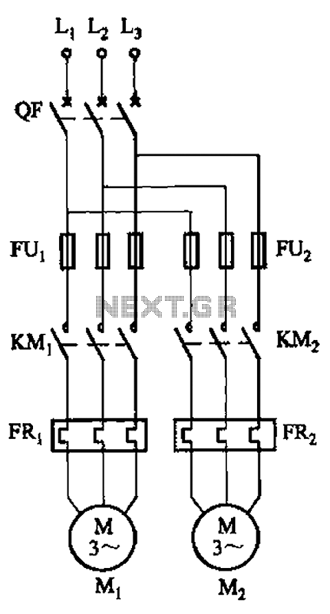
The circuit illustrated in Figure 3-64 operates with switch SA1 in the work position and switch SA2 in the standby position, allowing motor Mi to run while motor Mz remains on standby. In the event of downtime for motor...
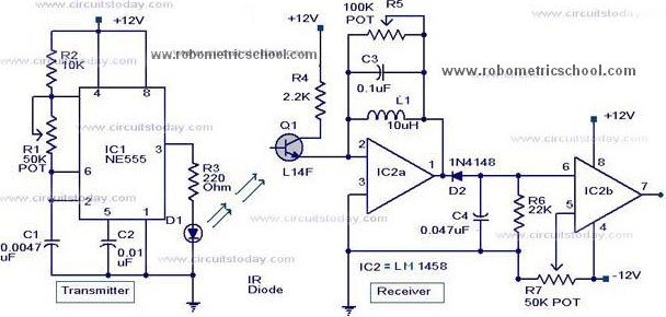
All components used in the Moving Sensor/Detector Schematic Diagram utilize the IC NE555 and the Phototransistor L14F. The primary component in this circuit is the IC NE555, along with an IR LED, the Phototransistor L14F, and the IC LM1458....
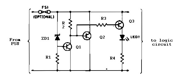
Logic overvoltage protection power supply. Refer to the designated page for an explanation of the power supply circuit diagram mentioned above. The logic overvoltage protection power supply is designed to safeguard sensitive electronic components from voltage spikes that could potentially...
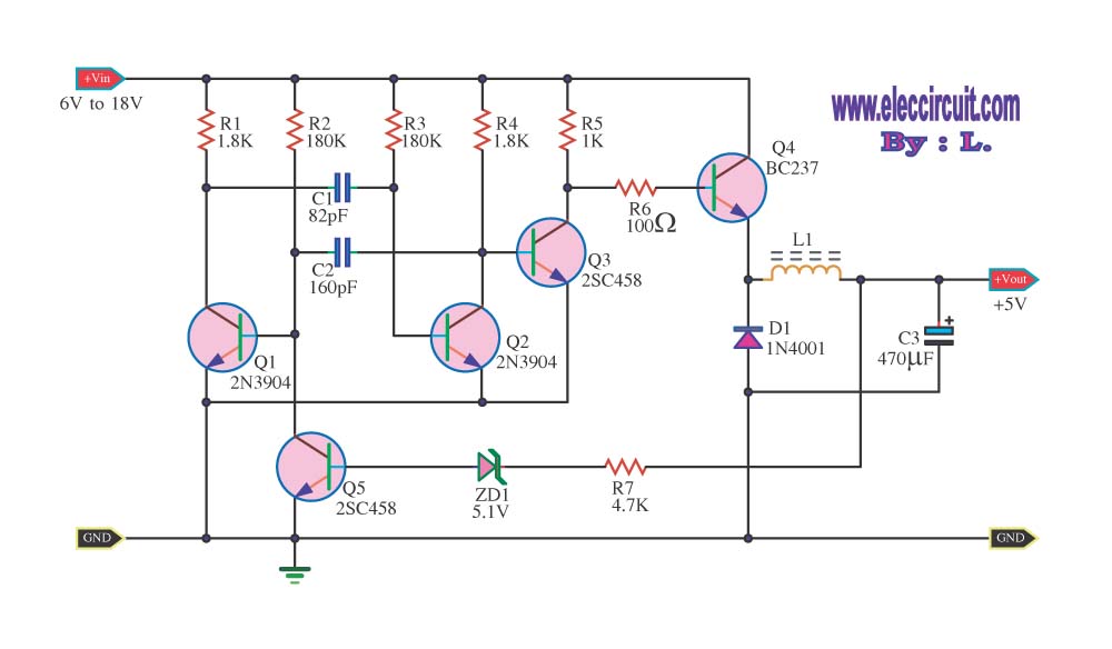
The circuit reduces voltage size or functions as a step-down voltage converter circuit, which is a DC regulated circuit model utilizing a switching converter. This design generates a specific voltage output. The step-down voltage converter, also known as a buck...

The circuit diagram illustrates a magnetic proximity switch, which is utilized in various applications. It features a magnetic reed switch (S1) as the proximity sensor. The circuit includes a monostable multivibrator utilizing the NE555 integrated circuit (IC1) and a...
For those who prefer convenience, it is possible to turn the bedroom light on or off without leaving the bed simply by clapping hands. This concept inspired the design of a clap-activated light control system. Various clap switch projects...