
TLE6282 H-Bridge And Half Bridge Driver IC

The circuit described operates as a highly efficient LED driver, leveraging the TinySwitch-III family’s capabilities for constant current regulation. The TNY279PN specifically is designed for off-line applications, featuring integrated high-voltage MOSFETs and a control circuit that allows for compact designs. The output current regulation is achieved through the feedback mechanism involving the operational amplifier and optocoupler, ensuring stable operation even under varying load conditions.
The use of a Zener diode for voltage feedback when the load is disconnected is a critical design feature that prevents overvoltage conditions, maintaining safe operation of the circuit. The sensing resistor (R11) plays a vital role in current measurement, providing necessary data for the operational amplifier to maintain the desired output current level.
The RCD clamp circuit is essential for protecting the MOSFET from voltage spikes that occur during the turn-off phase, which can be damaging if not properly managed. The Valley Fill circuit enhances the power factor and minimizes harmonic distortion, addressing the regulatory requirements for modern electronic devices.
Additionally, the frequency jittering function and the implementation of a shielded transformer winding contribute to EMI reduction, which is increasingly important in densely packed electronic environments. The pi filter further cleanses the output, ensuring compliance with stringent electromagnetic compatibility (EMC) standards.
This design exemplifies a robust and efficient approach to driving high-intensity LEDs, suitable for applications requiring reliable and consistent lighting performance while adhering to regulatory standards for harmonic distortion and electromagnetic interference.The converter shown uses a member of the TinySwitch-III family (U2, a TNY279PN) to provide up to 1. 8 A of load current to six, high-intensity, Luxeon LEDs (the LXHL series). The output voltage is slightly below the forward voltage drop of the LEDs Therefore, when the LEDs are connected to the supply, it operates in constant c urrent (CC) mode. If the LEDs are discon- nected from the supply, Zener Diode VR1 provides voltage feedback, which regulates the output voltage at about 13. 5 VDC. A 100 m © resistor (R11) senses the output current and an Opamp (U1) drives the Optocoupler (U3), which provides feedback to U2.
The TinySwitch-III family of devices regulate by disabling or skipping MOSFET switching cycles. As the load current reaches the current limit set-point threshold, U1 drives U3 on. The photo- Transistor in U3 pulls current out of the EN/UV pin of U2, causing it to skip switching cycles. Once the output current drops below the current limit set-point threshold, U1 stops driving U3, which stops pulling current out of the EN/UV pin of U2, and switching cycles are enabled again.
The TL431 (U4) provides a reference for U1 to compare against the voltage drop across R11. The output Diode (D9) is located in the lower leg of the transformer (T1) secondary winding to reduce EMI noise generation. An RCD clamp (R16, C4 and D13) protects the drain node of the MOSFET from the‚ flyback voltage spike.
The Valley Fill circuit (D5, D6, D7, C15, C16 and R15) limits the values of the third and fth harmonics of the line frequency current, which enables this supply to meet the requirements for Total Harmonic Distortion (THD) speci ed in IEC61000-3-2. The frequency jittering function in U2, a shield winding in T1 and a Y class capacitor (C8) across T1 reduce the generation of conducted EMI so that a simple pi lter (C13, L1, L2 and C14) allows the supply to meet EN55022B limits.
🔗 External reference
Related Circuits
A boost converter, such as the TPS61160/1, can be utilized with a 40V rated integrated switch FET to drive multiple LEDs in series. This configuration can help reduce output ripple. The TPS61160/1 is a highly efficient boost converter designed for...

This project involves controlling a small DC motor, sourced from an old personal cassette player, using the ATmega8 microcontroller. The ATmega8 features three PWM channels, of which two are utilized in this application. The PWM signals are sent to...
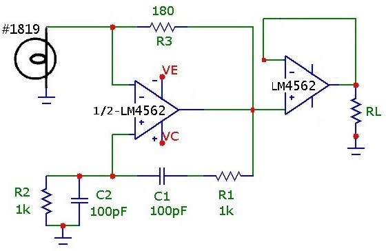
The classic Wien-Bridge oscillator, with incandescent lamp nonlinear stabilization, provides a low distortion sine wave source. A thorough and clear discussion of the Wien-Bridge oscillator is provided in Malvino's Electronic Principles. Using an inexpensive op-amp with sufficient bandwidth and...
A tutorial on the Wien Bridge Oscillator circuit, which utilizes an RC phase shift oscillator to generate sine waves. The Wien Bridge Oscillator is a well-known electronic circuit used to produce sine waves. It operates based on the principle of...

Conventionally, a MOSFET with a voltage rating of 1500V or a Half-Bridge configuration utilizing two MOSFETs rated at 800-900V is employed for Switch Mode Power Supply (SMPS) applications that require input voltages exceeding 380Vac. However, these methods present challenges,...

The schematic illustrates a 12 W Bridge Amplifier circuit diagram utilizing the TDA2007A, a class AB dual audio power amplifier. This amplifier is specifically designed for stereo applications in music centers, television receivers, and portable radios. As stated in...