
Toggle Switch Control Of Twin Coil Switch Machines

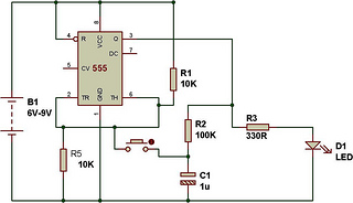
The described circuit utilizes a Double Pole Double Throw (DPDT) toggle switch, which serves as a manual control interface for a twin coil switch machine motor. This configuration allows for two distinct positions of the switch, enabling the user to select between two routes. Each pole of the switch is responsible for controlling one coil of the twin coil motor, ensuring that when the switch is toggled, one coil is energized while the other is de-energized. This action results in the physical movement of the switch machine, which can be used in model railroading or similar applications where track switching is required.
In addition to controlling the motor, the circuit is designed to integrate Light Emitting Diodes (LEDs) that provide visual feedback regarding the selected route. Each LED corresponds to one of the switch positions and illuminates when the respective coil is activated. This feature enhances user interface by providing immediate and clear indication of the switch's status.
To implement this circuit, the DPDT switch is connected such that the common terminals are linked to the power supply, while the two sets of switched terminals are connected to the coils of the motor. The LEDs are connected in parallel with the coils, ensuring that when a coil is energized, the corresponding LED lights up. Resistors may be included in series with the LEDs to limit current and prevent damage. The circuit design should also consider the specifications of the motor and LEDs, including voltage and current ratings, to ensure proper operation.
Overall, this circuit design effectively combines mechanical control with visual indicators, enhancing the functionality and user experience of the switch machine system.These circuits allow an ON-ON type DPDT toggle switch to control a twin coil switch machine motor. The handle of switch can then be used to indicate the route selected. The circuits are also able to control LEDs that could be used to indicate the selected route. 🔗 External reference
Related Circuits
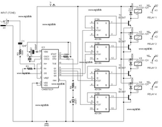
The following circuit illustrates a DTMF Remote Domestic System Control Circuit Diagram. Features: DTMF signals can be transmitted over a radio to control various domestic appliances. The DTMF (Dual-Tone Multi-Frequency) Remote Domestic System Control Circuit utilizes DTMF signaling for remote...
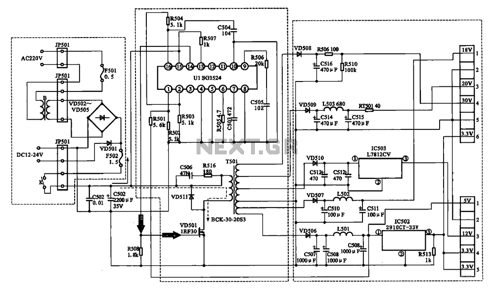
The Changhong DVB-2000 digital satellite receiver features a switching power supply circuit. This circuit primarily comprises a power input section, an oscillation switching circuit, and a DC output section. The power input circuit receives 22V AC from a step-down...
The reset switch on a computer is crucial. If an operating instruction threatens to disrupt the internal management of a computer, the reset button is often the only way to prevent a potential disaster. However, it can also lead...
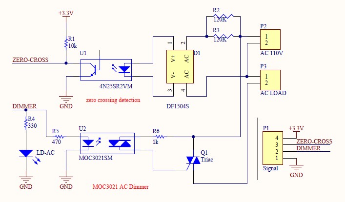
Have you verified whether you can see the zero crossings on your input pin? It may be beneficial to write a sketch that toggles the LED on pin 13 every 50 or 60 zero crossings. This should result in...
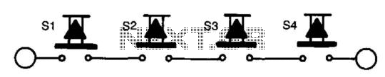
The circuit functions as a toggle switch, exhibiting two stable states: ON and OFF. When the circuit is in the ON state, it remains in that state until the switch is pressed again. The project is based on a...
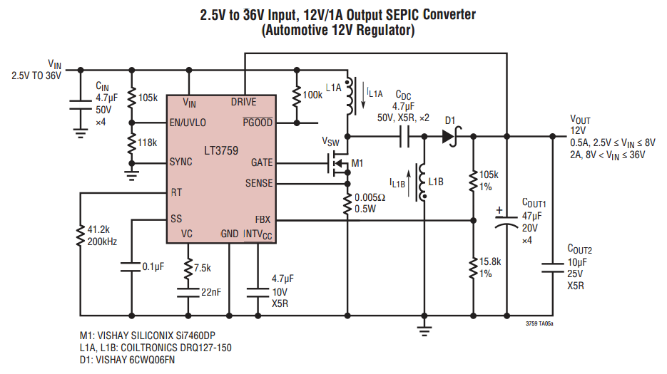
When VOUT is very low during startup or in the event of a short-circuit fault at the output, the switching regulator must operate at low duty cycles to keep the power switch current within the current limit range. This...