
microcontroller Arduino 230v Light bulb dimming

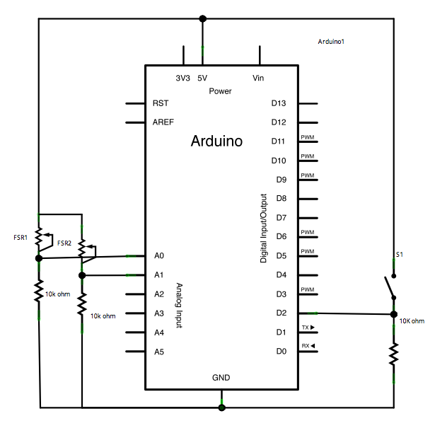
To observe zero crossings effectively on an input pin, it is essential to ensure that the setup is configured correctly. A zero crossing detector typically involves a comparator circuit that outputs a high signal when the input AC voltage crosses zero volts. This output can be connected to a digital input pin on the Arduino.
The suggested approach of toggling the LED on pin 13 can be implemented by writing an Arduino sketch that utilizes an interrupt service routine (ISR). The ISR should be triggered on the rising edge of the signal from the zero crossing detector. This will allow for precise timing, ensuring that the LED toggles at a frequency corresponding to the zero crossings detected.
In the sketch, the setup function should configure the pin connected to the zero crossing detector as an input and enable the appropriate interrupt. The loop function can remain empty or perform other tasks, as the LED toggling will be handled by the ISR. The timing of the toggling can be adjusted by counting the number of zero crossings detected, allowing for flexibility in the observed blink rate.
It is crucial to verify the type of Arduino board being used, as different models may have varying interrupt capabilities and pin configurations. This information will help ensure that the correct pins are utilized and that the code is compatible with the specific board's architecture.Did you check if you actually see the zero crossings on your input pin You might want to write a sketch that toggles the pin13 LED every 50 or 60 or zerocrossings. You should see a visible 1Hz blink. jippie Mar 3 `13 at 11:41 Which input pin did you use for attaching the zero crossing detector Notice that interrupt number may not be the same as input pin number and may interrupt pin numbers
may vary across Arduino board type. So which Arduino are you using jippie Mar 3 `13 at 11:44 @jippie i am new to this can you help me with it "Did you check if you actually see the zero crossings on your input pin You might want to write a sketch that toggles the pin13 LED every 50 or 60 or zerocrossings. " Daniel Euchar Mar 3 `13 at 11:49 🔗 External reference
Related Circuits
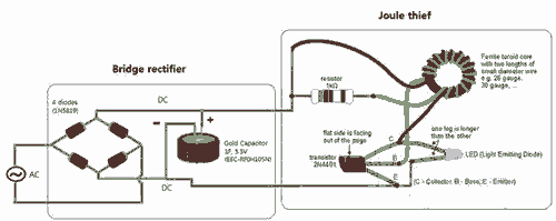
Breathe down and come out on the bright flashlight. In order to promote the voltage, pieces of a highly skilled Joule thief circuit have been used. The Joule thief circuit is a minimalist, low-power boost converter designed to extract energy...

This compact circuit is capable of distinguishing between light and darkness, making it highly beneficial for controlling the operation of signs, porch lights, or other devices in response to changing light conditions. The circuit operates using a light-dependent resistor (LDR)...
This sketch transmits an ASCII 'A' (byte value 65) upon startup and continues to do so until it receives a serial response from the computer. After receiving a response, it sends three sensor values as individual bytes and waits...

Most PN-junction diodes can be utilized as photodiodes. Although they are not specifically optimized for this purpose, they are functional. When reverse biased, a diode generates a small photovoltaic output that increases with light intensity. Light Emitting Diodes (LEDs)...
Read the generic sound level from an electret microphone. Several schematics utilize NPN transistors that yield an inverted output (~5V when quiet, ~0V when loud, with linear operation in between). However, a non-inverted output is desired, where a super...
Many of today's appliances feature displays and buttons. Instead of relying on motors and gears, numerous household items now incorporate embedded microcontrollers. This exploration focuses on how to experiment with microcontrollers at home. Microcontrollers serve as the central processing units...