
Toggle Switch No.1 - Cmos 4013

This circuit functions as a simple toggle switch, utilizing a momentary action push-to-make switch to control the state of a relay. The relay serves as an electromechanical switch, enabling the control of higher voltage or current loads while maintaining low-voltage control circuitry. The inclusion of the CMOS 4013, a dual D-type flip-flop, allows for the toggle functionality, where one half of the IC is configured to change state with each button press.
The circuit design requires careful selection of the relay based on the voltage and current specifications of the load to be controlled. The relay's coil must match the supply voltage, which can vary from 5 to 15 volts, providing flexibility for different applications. The visual indication provided by the LED enhances usability by allowing the user to easily determine the relay's status.
In terms of safety, the warning against using the on-board relay for mains voltage switching is crucial. The proximity of low-voltage components to relay contacts poses a risk of electrical shock or damage. For applications involving mains voltage, it is recommended to utilize a relay that is rated for such use and to install it in a manner that ensures adequate isolation from the control circuitry. This could involve using a separate enclosure or mounting the relay on a different board entirely.
Overall, this circuit is ideal for applications requiring a simple toggle switch mechanism, offering versatility and ease of use while emphasizing the importance of safety in higher voltage applications.This simple circuit will energize and de-energize a relay at the push of a button. Any type of momentary action push-to-make switch can be used. Pushing the button once - will energize the relay. And pushing it a second time - will de-energize the relay. I`ve drawn the circuit with a single pole relay. But you can use a multi-pole relay if it suit s your application. Only one half of the Cmos 4013 is used. So you could construct two independent toggle switches with a single IC. The circuit will work at anything from 5 to 15-volts. All you need do is select a relay with a coil voltage that suits your supply. The LED provides a visual indication that the relay is energized. In effect - it tells you whether the switch is on or off. It`s not necessary to the operation of the circuit. If you wish you may leave out R3 and the LED. Do not use the "on-board" relay to switch mains voltage. The board`s layout does not offer sufficient isolation between the relay contacts and the low-voltage components. If you want to switch mains voltage - mount a suitably rated relay somewhere safe - Away From The Board.
🔗 External reference
Related Circuits
Using just two NAND or inverter gates, it is possible to build a D-type (or toggle) flip-flop with a push-button input. At power-up, the output of gate N2 is at a logical 1, ensuring that transistor T2 is switched...
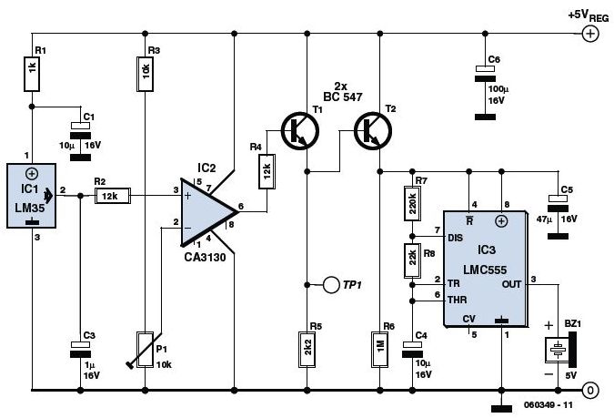
The circuit utilizes a precision integrated temperature sensor, the LM35 (IC1), which provides a linear and directly proportional output in millivolts over a temperature range of 0 to +155 degrees Celsius. This sensor can be incorporated into fire smoke...
The circuit operates based on a desired temperature setting. It can be utilized for various applications, such as turning on a fan at a specified temperature or activating an emergency temperature alarm. The power supply for the circuit can...

The pulse transformer T1 utilizes a ferrite core, specifically M2500NMS-2 or M2000NM9, with dimensions of Sh5h5 (cross-section of the magnetic coils at 5G—5 mm with a center gap). The winding wire is of type PEL-2. The primary winding consists...
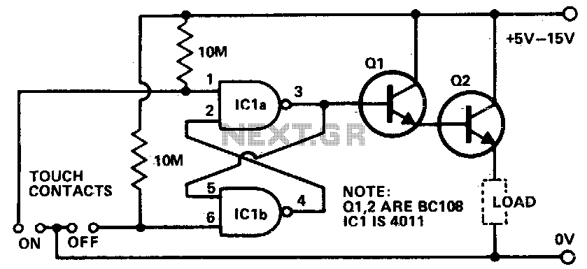
Touching the on contacts with a finger brings pin 3 high, turning on the Darlington pair and supplying power to the load (transistor radio, etc.). Q1 must be a high-gain transistor, and Q2 is chosen for the current required...
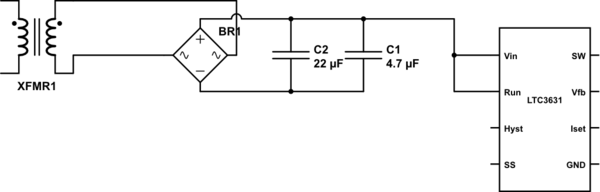
The leads from the transformer to the circuit are quite long (>5m). The 110V side of the transformer has been switched off frequently, which likely caused a spike on the secondary (24V) side. The input pin of the LTC3631...